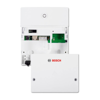
Installation
MB LAN – 6 720 802 641 (2012/08)
6
2.3 Specification
3Installation
3.1 Installation
B Removing the cover (Æ Fig. 3, page 32)
B Fitting the module (Æ Fig. 4, page 32)
B Fixing the module (Æ Fig. 5, page 32)
3.2 Electrical connections
Connections and interfaces
Legend to Fig. 6, page 33:
7,5 V DC Power supply unit connection
HT 2-wire BUS system connection
LAN LAN connection (RJ45)
RESET RESET button
Pre-assembling the grommets and connecting the cables
B Open out the grommets to match the cable diameter and make an
incision on one side (Æ Fig. 7, page 33).
B Fit the grommets and connect the cables (Æ Fig. 8, page 33).
BUS connection
B Connect BUS subscribers with two BUS connectors in series
(Æ Fig. 6, page 33) or BUS subscriber [B] with one junction box [A]
in a star configuration (Æ Fig. 9, page 33).
B All LV leads must be routed separately from cables carrying mains
voltage to avoid inductive interference (minimum separation
100 mm).
B In case of external inductive interference, shield the cables.
This ensures that the cables are shielded from external interference
(e.g. heavy current cables, overhead wires, transformer stations,
radio and television set, amateur radio stations, microwave ovens
etc).
B Fit the cover and plug in the power supply unit supplied.
4 Commissioning
The router must be configured as follows:
• DHCP enabled
• Ports 5222 and 5223 not blocked
• Free IP address available
• Address filtering (MAC filter) matched to the module.
The module automatically obtains an IP address from the router. The
name and address of the target server are stored in the standard settings
of the module. If there is an internet connection, the module
automatically logs into the Junkers-Server.
The router does not necessarily have to be connected to the internet.
The module can also be operated using the local network only. If this is
the case, access to the heating system via the internet or automatic
updates of the module software are not possible.
The first time the JunkersHome App starts, you will be prompted to
enter the factory-set login name and password. These login details are
printed on the module data plate.
Data plate
Legend to Fig. 10, page 33:
[1] Data plate with login details, MAC address and serial number
[2] DIP switch (no function)
Testing the connection (with heating circuit 1 logged on)
You can check whether the module is communicating correctly with the
heating system.
B Press the RESET button (Æ Fig. 6, page 33)briefly in order to change
the operating mode for heating circuit 1 at the controller.
The controller display shows the modified operating mode (heating
or economy ).
B To conclude the connection test, reinstate the required operating
mode.
Resetting personal settings
If you have forgotten your personalised login name or password:
B Hold down the RESET button (Æ Fig. 6, page 33) for at least 5
seconds.
The factory-set login details are restored.
5 Environmental protection/Disposal
Environmental protection is a key commitment of the Bosch Group.
Quality of products, efficiency and environmental protection are equally
important objectives for us. Laws and regulations aimed at protecting
the environment are strictly adhered to.
To protect the environment we will, subject to economical aspects, use
the best possible technology and materials.
Packaging
We participate in the recycling programmes of the countries in which our
products are sold to ensure optimum recycling.
All of our packaging materials are environmentally compatible and can
be recycled.
Specification
Dimensions (W×H×D) 151×184×61mm (further
dimensions Æ Fig. 2, page 32)
Maximum cross-section
(terminals)
2.5 mm
2
Rated voltages:
• BUS
• Module power supply
• 12 V to 15 V DC (reverse polarity
protected)
• Plug power supply unit supplied
230 V AC/7.5 V DC, 700 mA
Interfaces • 2-wire BUS
• LAN: 10/100 MBit/s (RJ45)
Power consumption 1.5 VA
Permissible ambient
temperature
0 ... 50 °C
IP rating IP20
Table 2
If the maximum cable length of the BUS connection
between all BUS subscribers is exceeded, the system
cannot be commissioned.
Cable length Conductor cross-section
≤ 80 m 0.40 mm
2
≤ 100 m 0.50 mm
2
≤ 150 m 0.75 mm
2
≤ 200 m 1.00 mm
2
≤ 300 m 1.50 mm
2
Table 3 Total BUS length
During commissioning, the LED on the module
illuminates in red if neither the BUS nor the LAN
connection is made.

 Loading...