Do you have a question about the Bosch KT700VCI and is the answer not in the manual?
Explains warning notices, their structure, meaning, and symbols used in the manual.
Details warnings and symbols found directly on the VCI product itself.
Defines the target audience and necessary qualifications for using the VCI.
Highlights hazards associated with electric shocks and necessary safety measures.
Discusses risks from both low and high voltages in vehicles and safety precautions.
Focuses on specific dangers and safety measures for hybrid/electric vehicles.
Explains WLAN basics, interference, and best practices for connectivity.
Provides guidance on setting up and using wireless access points for optimal connection.
Lists the minimum and recommended hardware specifications for the PC.
Step-by-step instructions for installing the VCI software on a PC.
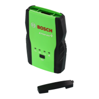
Identifies and describes the function of various indicator lamps and buttons on the VCI host.
Identifies and labels the diagnosis, USB, and network communication ports on the VCI host.
Explains how to establish a diagnostic connection between VCI, PC, and ECU.
Details the connection setup for performing a selfcheck of the VCI.
Outlines the connection procedure for upgrading the VCI firmware.
Covers language, system information, user, proxy, and activation settings.
Details configuration for language, user info, and proxy settings.
Explains the process of activating the VCI product for full functionality.
Details steps for updating the application software and diagnostic database.
Explains how to perform a manual upgrade of the VCI's internal firmware.
Configures communication settings for USB, LAN, and WLAN connections.
How to view VCI details and perform self-diagnostics.
Instructions for replacing vehicle logos on the display.
Lists prerequisites for performing vehicle diagnostics.
Describes the four available power supply modes for the VCI host.
Guides on selecting vehicle models and systems for diagnosis.
Overview of the diagnosis interface and reading vehicle version information.
Process to read, view help, and clear Diagnostic Trouble Codes from the ECU.
Captures and displays vehicle conditions at the time of a fault.
Displays real-time data values from vehicle sensors and components.
Allows switching between numeral, waveform, and control display modes for data streams.
Records ECU data over extended periods for analysis.
Tests component functionality and accesses advanced ECU modification features.
Options for printing current screen, detection records, or diagnostic reports.
Saves printed content as an image file (JPG).
Allows browsing diagnostic images and capturing screenshots.
Provides online help and a channel for user feedback.
Recommendations for cleaning the VCI host using soft cloth and neutral detergent.
Guidelines for proper storage and periodic operation of the VCI.
Lists technical specifications of the VCI host, including size, weight, and power.
| Category | Medical Equipment |
|---|---|
| Type | Ventilator |
| Model | KT700VCI |
| Brand | Bosch |
| Oxygen Concentration | 21-100% |
| Display | LCD |
| Respiratory Rate Range | 5-60 bpm |
| Alarms | Apnea, Power failure |
| Battery Backup | Up to 4 hours |
| Tidal Volume Range | 50-1500 ml |