PAVIRO Call Stations Connection | en 27
Bosch Security Systems 2018.04 | 04 | F01U306899
socket via the enclosed network cable (3 m). The following
image shows the assignment of the CST BUS port and the
corresponding RJ-45 connector.
Notice!
It is mandatory to use shielded twisted pair cables for
connecting: CAN (4, 5), AUDIO CONTROLLER TO CALL
STATION (3, 6) and AUDIO CALL STATION TO CONTROLLER (7,
8).
8:
2:
4: CAN_H (+)
5: CAN_L (-)
1 8
7:
1: +24V DC
3:
6:
AUDIO CALL STATION TO CONTROLLER -
AUDIO CALL STATION TO CONTROLLER +
AUDIO CONTROLLER TO CALL STATION -
AUDIO CONTROLLER TO CALL STATION +
GND (CAN_GND)
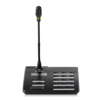
Figure6.1: Pin assignment of CST BUS port
8:
5: CAN_L (-)
3:
2: CAN_GND
1: +24V DC
7:
8
1
4: CAN_H (+)
6:
GND
( )
AUDIO CALL STATION TO CONTROLLER -
AUDIO CALL STATION TO CONTROLLER +
AUDIO CONTROLLER TO CALL STATION -
AUDIO CONTROLLER TO CALL STATION +
Figure6.2: Pin assignment of CST BUS connector
Power supply
The minimum supply voltage of the call station is 15 V DC. As
the minimum supply voltage of the controller is 18 V DC, the
maximum allowable voltage drop at the connection wiring
between controller and call station is 3 V DC. Please refer to the
technical data (e. g. supply current) of the call station or call
station extension to select appropriate connection cables,
especially for long cable runs.
If the voltage drop is higher than 3 V DC, the minimum supply
voltage of the controller has to be increased to ensure the
minimum supply voltage of the call station.
 Loading...