Plena Voice Alarm System System overview | en 21
Bosch Security Systems B.V. Installation and Operation manual 9922 141 1037x (V2.16) | V0.6 | 2011.09
19. Volume override:
Three contacts (NC/24V/NO) to connect a fail-safe or a power-saving 4-wire volume
override (see section 5.1.7 ).24 V DC output One 24 V(DC) output.
20. Power amplifier failure:
Two pins (NC relays) to report a failure of the power amplifier.
21. Trigger outputs:
Two general purpose trigger outputs. For future use.
22. Back-up power inlet:
An inlet to connect a back-up power supply to the voice alarm router (see section 5.2.6 ).
23. Back-up power inlet:
An inlet to connect a back-up power supply to the voice alarm router (see section 5.2.6 ).
24. External power amplifier 2 (input):
An input to connect an external power amplifier (see section 10.1.2 ). These pins are
used in combination with the external power amplifier output (no. 18).
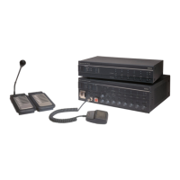
3.4 Call Station
The Call Station can be connected to the Plena Voice Alarm System to make business calls.
The maximum number of call stations in a Plena Voice Alarm System is 8.
Figure 3.5 Call Station
3.4.1 Buttons
Each call station has zone select buttons and a push-to-talk (PTT) button. The zone select
buttons can be configured for selecting zones and zone groups in the system. To the PTT
button, a pre and post chime can be assigned that is played at the start or at the end of the
business call.
3.4.2 Supervision
The call station is not supervised. For compliance to evacuation standards, the Plena Voice
Alarm System disables the call station during emergency calls.
 Loading...

