Plena Voice Alarm System System overview | en 27
Bosch Security Systems B.V. Installation and Operation manual 9922 141 1037x (V2.16) | V0.6 | 2011.09
3.8 Remote Control Extension
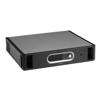
Figure 3.11 Front and rear views of the remote control extension kit
?See Figure 3.11 for an overview of the controls, indicators and connectors on the remote
control extension.
1. Power LED/VU Meter:
A combined power indicator and VU meter. The green power LED is lit if the remote
control extension is connected to the mains or back-up power and switched on. The VU
meter indicates the call level: 0 dB (red), -6 dB, -20 dB (yellow).
2. Fault indicators:
Eight yellow system fault LEDs (Processor reset, Network, Call/EMG, Music/Spare,
Ground short, Input, Mains, Battery) and twelve yellow loudspeaker line fault LEDs. Fault
indication is only possible if supervision is enabled (see section 7.5.3 ).
3. Emergency call zone selectors:
Six buttons to select the zones to which the emergency call must be distributed (see
section 7.4 ). Each button has a green and a red LED. The six red LEDs indicate the zones
that are selected for the emergency call. The six green LEDs indicate the zones in which a
business call is running.
4. BGM zone selectors:
Six buttons to select the zones to which the BGM is distributed (see section 7.2 ). Each
button has a green LED. The six green LEDs indicate the zones to which BGM is
distributed.
5. Ground:
A connection to electrically ground the remote control extension.
 Loading...

