Bosch Security Systems | 2006-06 | 9922 141 10377 en
Plena Voice Alarm System | Installation and User Instructions | Equipment en | 30
5.3.3 Voice alarm routers
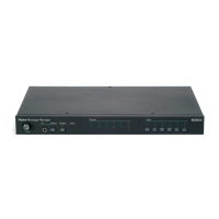
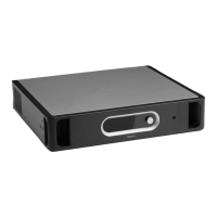
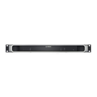
The voice alarm controller has 1 socket for LBB1992/00
Voice Alarm Routers. Use shielded Cat-5 Ethernet
cables with RJ45 plugs to connect a voice alarm router
to the voice alarm controller. When the system requires
more than 1 voice alarm router, use the system sockets
on the voice alarm router to make loop-throughs. See
figure 5.5 for connection details.
5.3.4 External power amplifier
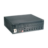
The voice alarm controller has 1 external power
amplifier output (line level, 1 V) and 1 external power
amplifier input (100 V) to connect an external power
amplifier (see figure 5.6). The function of the external
power amplifier (e.g. an LBB1930/00 Plena Power
Amplifier) depends on the channel mode for which the
voice alarm controller is configured (see section 17.5).
figure 5.5: Connecting routers
Note
Each connected voice alarm router must have a
unique ID (see 20).
itoring
e
aker
ontr
ol Panel
Router
W
arning
T
his apparatus m
u
st be earthed
1
2
Firmware up
ality
Netherlands
3
Termination
1
...9
ID
Router
Rated input
Li
ne fuse
ster 2
In
Out
Made
i
On
Of
f
Firmw
a
re
up
a
l
i
t
y
N
e
the
rl
ands
3
Termin
a
tion
1
...9
I
D
Router
Ra
ted i
np
ut
Line f
u
s
e
ster 2
In
Out
Made
i
On
Of
f
figure 5.6: Connecting an external power amplifier
100V 70V 0
line in line out
12
3
12
3
GND GND++
--
COM
NC
TRG2
Z2
Z3
Z4
Z5
Z6
Ext
Booster
In
DC In
TRG 1
Int
Booster
Out
24V
Fault
Call
External Booster
Out
100 V
0
100 V
0
100 V
0
100 V
0
100 V
0
100 V
0
24V
70V
Z2
Z3
Z4
Z5
Z6
GND
NC
COM
NO
NC
COM
NO
NO
100 V
0
Call out
0
100 V
0
100 V
0
100 V
0
100 V
0
100 V
0
Z2
Z3
Z4
Z5
Z6
NO
Volume Override
100 V

 Loading...
