Bosch Security Systems | 2004-06 | 9922 141 10371en
Plena Voice Alarm System | Installation and User Instructions | System units en | 21
3 System units
3.1 Introduction
The Plena product family comprises various units that
can be used to configure a Plena Voice Alarm System,
to meet your specific configuration requirements. This
chapter first describes the functionality of each of the
Plena units and explains their usage. Further on in this
chapter, for each of the units, an overview is provided of
the connectors, controls and indicators.
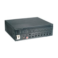
3.2 Voice alarm controller
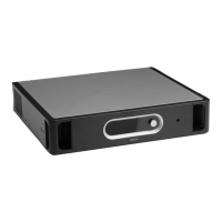
The voice alarm controller (LBB1990/00) is the heart of
the Plena Voice Alarm System. The voice alarm
controller (further referred to as “controller”) centrally
manages and distributes emergency calls, business calls
and background music (BMG). A single controller is
able to serve and manage 6 loudspeaker zones. If more
zones are to be served, extra routers can be connected
(see section 3.3). Like this, up to a maximum of 60 zones
can be served. The controller is equipped with an
internal booster (see section 3.2.4) and an integrated
message manager (see section 3.2.5). All Plena units to
be used, can be connected to the central controller.
3.2.1 Trigger inputs
The rearside of the controller provides a terminal block
for the connection of 6 EMG and 6 business trigger
inputs. The EMG trigger inputs have a higher priority in
being served, than the business trigger inputs. The
trigger inputs can be used to signal events to the
controller. To each trigger input, a prerecorded message
can be assigned and broadcast to one or more zones or
zonegroups.
To connect the trigger inputs, refer to section 4.7.
3.2.2 Loudspeaker zones
The controller can serve 6 loudspeaker zones. In
compliance with IEC60849, the supply to each zone is
redundantly designed. For this purpose, on the rearside
of the controller, there are two zone output terminal
blocks (A and B). To connect the zone outputs, refer to
section 4.8.
figure 3.1: Voice alarm controller (LBB1990/00)
Note
Refer to the Configuration Software Manual
(9922 141 10381) to configure the trigger
inputs.
figure 3.2: Trigger inputs
LBB1990/00
Voice Alarm Controller
10k
10k
Trigger input/24V DC out
Business
Emergency
123456
123456
123456
24V
DC out
VOX
Switch
VOX Switch
123456
24V
DC out

 Loading...
