Bosch Security Systems | 2004-06 | 9922 141 10371en
Plena Voice Alarm System | Installation and User Instructions | Installation en | 40
4.11 Connecting line output
The voice alarm controller has one line output (see
figure 4.14). This output has a double cinch socket. Both
cinch sockets contain the same, mono signal, which
consists of the current BGM and calls. The line output
can be used to connect the controller to a recording
device (e.g. a tape-deck).
4.12 Connecting trigger outputs
The controller has 3 trigger output contacts. The trigger
output contacts (see figure 4.15) can be used to indicate
the current state of the system to third-party equipment,
to trigger particular actions, e.g. activating a signalling
light or a beeper if the system has entered the
emergency state (see section 6.6).
The trigger output contacts are implemented as internal
relays offering a normally closed (NC) and a normally
open (NO) contact. By default, all contacts are de-
energized (NC is connected to COM). On entering one
of the states, as mentioned in table 4.8, the
corresponding output contact is energized (NO is
connected to COM).
figure 4.14: Connecting line output
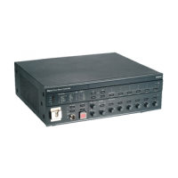
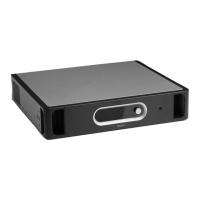
LBB1990/00
Voice Alarm Controller
figure 4.15: Connecting trigger outputs
table 4.8: Trigger outputs
Contact Description
EMG Emergency state (see also section
4.12.1).
Fault Fault state (see also section
4.12.2).
Call Call state (see also section 4.12.3).
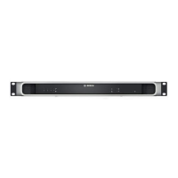
LBB1990/00
Voice Alarm Controller
NC
TRG2
TR
24V
EMG
Fault
Call
Z1
Z2
Z3
Z4
Z5
Z6
NC
COM
NO
NC
COM
NO
NC
COM
NO
NO
V
NC
COM
NO

 Loading...
