4
17. Use push sticks, vertical and horizontally mounted
feather boards (spring sticks) and other jigs to
hold down the workpiece. Push sticks, feather
boards and jigs eliminate the need to hold the
workpiece near the spinning bit.
18. Piloted bits along with the starter pin are used
when routing internal and external contours on
the workpiece. Use the auxiliary bit guard when
shaping material with the starter pin and piloted
bits. The starter pin and bearing of the piloted bit
assist in maintaining control of the workpiece.
19. Do not use the table as workbench or
worksurface. Using it for purposes other than
routing may cause damage and make it unsafe
to use in routing.
20. Never stand on the table or use as ladder or
scaffolding. Table could tip or the cutting tool could
be accidentally contacted.
21. Use only Bosch replacement parts. Any others may
create a hazard.
Additional Warnings for Router Tables
If an extension cord is necessary, a
cord with adequate size conductors that is capable of
carrying the current necessary for your tool must be
used. This will prevent excessive voltage drop, loss of
power or overheating. Grounded tools must use 3-wire
extension cords that have 3-prong plugs and receptacles.
NOTE: The smaller the gauge number, the heavier the cord.
RECOMMENDED SIZES OF EXTENSION CORDS
120 VOLT ALTERNATING CURRENT TOOLS
Tool’s
Ampere
Rating
Cord Size in A.W.G.
Wire Sizes in mm
2
3-6
6-8
8-10
10-12
12-16
18 16 16 14 .75 .75 1.5 2.5
18 16 14 12 .75 1.0 2.5 4.0
18 16 14 12 .75 1.0 2.5 4.0
16 16 14 12 1.0 2.5 4.0 —
14 12 — — — — — —
25 50 100 150 15 30 60 120
Cord Length in Feet Cord Length in Meters
Important Information About Extension Cords
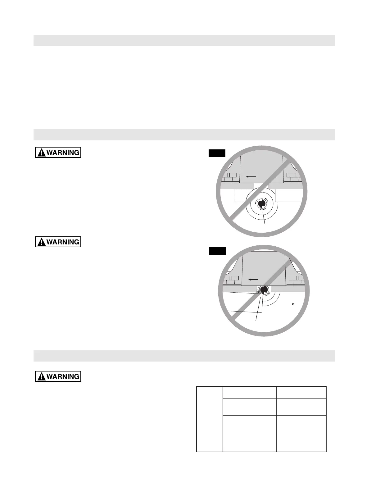
Improper Fence Location and Workpiece Feed
The fence and/or workpiece are
improperly located anytime it would result in:
• The front of the bit is exposed during the actual cutting
(Fig. A).
• “Climb-cutting” - The bit must not enter the workpiece in
the same direction as the feed direction, which is likely to
cause the workpiece to "climb" and may lead to loss of
control during operation (Fig. B).
"Fence Traps": One type of improper fence location war-
rants special attention: "Fence traps" happen when the
fence is positioned so far back that front side (power switch
side) of the workpiece would be behind the router bit.
Fence traps are dangerous for
two reasons:
• Exposure of the bit on the front side (power switch side)
of the workpiece.
• Likeliness of climb cut, which can cause loss of control.
Fig. A shows a fence trap.
Do not feed the workpiece from left to right: (Fig. B)
• It would cause climb-cutting.
• It would be difficult to keep the workpiece against the
fence faces because the bit rotation would push the work-
piece away from the fence.
FIG. A
FIG. B
WORKPIECE
EXPOSED BIT
WORKPIECE
CLIMB-CUTTING
DIRECTION
OF FEED
CORRECT
DIRECTION
OF FEED
INCORRECT
DIRECTION
 Loading...