-30-
Secure the laser receiver LR40 at the correct
height:
– Either to a wall or to another surface by
means of magnets or the suspension hooks
on the laser receiver,
– or to a securely fastened measuring rod
(43) with the holder for the laser receiver.
For this, please observe the operating instruc-
tions for the laser receiver.
Align the laser level so that the X-axis indica-
tor imprinted on the laser level with the “+”
side is pointing to the laser receiver. For this,
the X-axis must be perpendicular to the laser
receiver.
To start calibration:
– For calibration via the Bosch Levelling Re-
mote App: Switch on the measuring tool.
Start calibration in the app. Follow the in-
structions in the app.
– For calibration without the app: Switch on
the measuring tool and the laser receiver.
Make sure that both of these are connect-
ed via Bluetooth®. Start the calibration by
pressing the on/off button on the laser re-
ceiver and the center line mode button on
the laser receiver at the same time. “CAL”
will appear on the display of the laser re-
ceiver.
Press the center line mode button on the laser
receiver to cancel the calibration, if required.
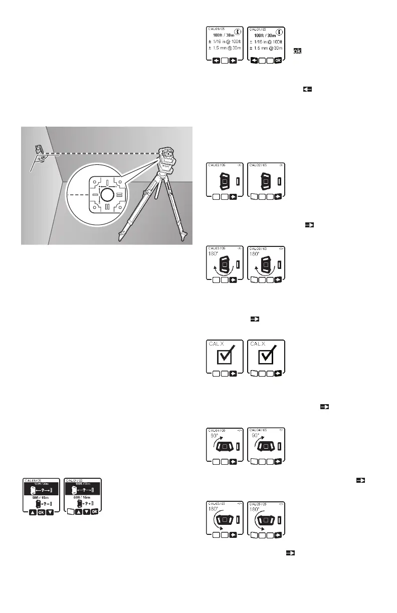
In the menu that ap-
pears in the measuring
tool display after start-
ing the calibration, se-
lect the existing distance between the mea-
suring tool and the laser receiver. To do this,
press the buttons ▲ (4) or ▼ (3). Confirm your
selection with by pressing the slope button
(14).
To confirm the select-
ed measuring distance
( ), including the cor-
responding levelling
accuracy, on the display which appears, press
the slope button (14). To go back to selecting
the measuring distance ( ), press the line
operation button (5).
Align the height of the laser receiver so that
the variable laser beam (8) on the laser re-
ceiver is indicated as “centered” (see operat-
ing instructions for the laser receiver). Secure
the laser receiver at this height.
Check whether the la-
ser level and laser re-
ceiver are aligned with
each other, as illustrat-
ed on the display (the “+” side of the X-axis is
aligned to the laser receiver). Start the cali-
bration of the X-axis with by pressing the
slope button (14).
If this step appears on
the display, rotate the
laser level 180° so that
the “–” side of the
X-axis is aligned to the laser receiver. For each
rotation, take care not to change the height
and position of the laser level. Confirm the ro-
tation with by pressing the slope button
(14). Calibration of the X-axis continues.
The indicator opposite
will appear if both
sides of the X-axis have
been successfully cali-
brated. XOK will appear on the display of the
laser receiver.
Continue the calibration with
by pressing
the slope button (14).
To calibrate the Y-axis,
rotate the measuring
tool 90° in the direc-
tion of the arrow so
that the “+” side of the Y-axis is directed at the
laser receiver. Confirm the rotation with by
pressing the slope button (14).
If this step appears on
the display, rotate the
measuring tool 180°
so that the “–” side of
the Y-axis is aligned to the laser receiver. Con-
firm the rotation with by pressing the slope
button (14). Calibration of the Y-axis contin-
ues.