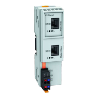
9.4 Bus bases
The IndraControl XM42 is attached to the bus base XA-BS03. The bus base XA-
BS03 connects the IndraControl XM42 to the S20 modules on the right control
side and to the extension modules on the left control side. The bus base XA-
BS03 is provided upon delivery.
10 Mounting, demounting and electric installation
10.1 Installation notes
Module destruction due to electrostatic dis-
charge
The XM42 control contains components that can be damaged or destroyed by
electrostatic discharge. Comply with the required safety measures against elec-
trostatic discharge (ESD) acc. to EN 61340-5-1 when operating the control.
● Mounting location
The XM42 control has the degree of protection IP20 and is thus intended for
the use in a closed control cabinet or control box (terminal box) of the degree
of protection IP54 or higher.
● Mounting rail
Mount the XM42 control on a 35 mm standard mounting rail. The preferred
overall height of the mounting rail is 7.5 mm (corresponds to TH 35-7.5 acc.
to EN 60715).
Mount the control and the bus base as described in the following.
The fastening distance of the mounting rails may not exceed 200 mm. This
distance is required to ensure stability while mounting and demounting the
control or the S20 I/O modules.
Fig. 10-1:
Mounting rail fastening (in mm)
Electronic damage due to fastening elements
Danger of malfunction
If the fastening elements (screws, rivets,...) are too high, the bus bases do not
correctly engage on the mounting rail. Use only elements with a structural
height of up to 3 mm to fasten the mounting rail.
● End clamp
16/65
Mounting, demounting and electric installation
IndraControl XM42 Controls
Bosch Rexroth AG R911345566_Edition 03

 Loading...


