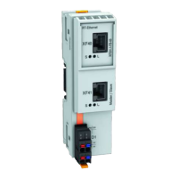
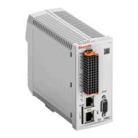
8.5 CN - CANopen
Display Elements CANopen
LED Significance Color Description
H4 Run
Green
Signals operating states; see Functional
Description of firmware
H5 Error
Red
Signals error states; see Functional De‐
scription of firmware
Tab. 8-23: Significance of Display Elements for CANopen
Main Features
Feature CANopen
Compatibility According to EN 50325-4
Max. possible number of nodes 127 nodes
Bus Topology Line topology
Bus terminator (ISO 11898) 124 ohm each, 1%, 200 mW; connect at both
bus ends to X61.2 and X61.7
Transmission medium 2 twisted two-wire lines (4-pin) with shield
Max. allowed bus (line) lengths Depending on bit rate
Recommended connection cable Our RKS number or third-party type
Tab. 8-24: Main Features
Bus Lengths Depending on Bit
Rates
Bit rate
[kBaud]
Max. allowed network dimension
[m]
1000 25
800 50
500 100
250 250
125 500
50 1000
20 2500
10 5000
Tab. 8-25: Network Dimension
Bosch Rexroth AG DOK-INDRV*-CXX02******-PR03-EN-P112/143
IndraDrive Control Sections CSB02, CSE02, CSH02, CDB02
Technical data - functions
Courtesy of CMA/Flodyne/Hydradyne ▪ Motion Control ▪ Hydraulic ▪ Pneumatic ▪ Electrical ▪ Mechanical ▪ (800) 426-5480 ▪ www.cmafh.com

 Loading...


