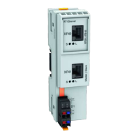
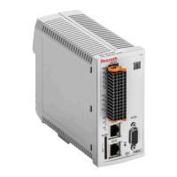
5.6.2 Front view with connection points
Front view
(example)
Connection
point
1)
Stranded
wire
[mm²]
AWG Description
X4.1
X4.2
0.25–0.5 - Encoder evaluation EC
X8* 0.25–0.5 - Encoder evaluation EC
Encoder emulation EM
X10* 0.25–0.5 - Encoder evaluation EC
Encoder emulation EM
X24 P2,
X25 P1
- - Multi-Ethernet communication ET
X30* 0.25–0.5 - PROFIBUS communication PB
X31 0.75–1.5 20–14 Digital inputs/outputs
Probe input
X32 0.75–1.5 20–14 Analog inputs
X33 0.75–1.5 20–14 Voltage input (24V, 0V)
Bb relay
X36 0.75–1.5 20–14 Digital inputs and outputs; analog out‐
puts (voltage)
X37* 0.75–1.5 20–14 Digital inputs/outputs
X38* 0.75–1.5 20–14 Analog inputs/outputs
X41.1*
X41.2*
0.75–1.5 20–14 Safety technology S4, S5, SB
(With SB: X41, X42, X43 not availa‐
ble; LEDs available)
X42.1 /
X43.1*
X42.2 /
X43.2*
- -
X48.1*
X48.2*
0.75–1.5 20–14 Safety technology
(Only available in conjunction with
safety technology S4, S5, SB)
X49.1*
X49.2*
0.75–1.5 20–14 Safety technology L3
H1 - - Interface for control panel
1) Connection points of axis 1 have the extension ".1" (e.g. X4.1);
connections of axis 2 have the extension
".2" (e.g. X4.2)
* Optional connection point; the optional connection points are
marked with gray background color in the exemplary figure
Tab. 5-13: CDB02 connection points
DOK-INDRV*-CXX02******-PR03-EN-P Bosch Rexroth AG 41/143
IndraDrive Control Sections CSB02, CSE02, CSH02, CDB02
Rexroth IndraDrive control sections
Courtesy of CMA/Flodyne/Hydradyne ▪ Motion Control ▪ Hydraulic ▪ Pneumatic ▪ Electrical ▪ Mechanical ▪ (800) 426-5480 ▪ www.cmafh.com

 Loading...


