5-6 BZM auxiliary bleeder module ECODRIVE DKC02.1 Drive Controller
DOK-ECODRV-DKC02.1****-PRJ2-EN-P
5.3 Technical data
Designation
Unit
1
kW
Value
40
P
BM,BZM
kW
40
W
MAX,BZM
kWs
DC 24 V ±20%
U
N,BZM
V
90
I
N,BZM
mA
TB0209D4.fh5
P
BD,BZM
Symbol
Continuous bleeder output
Peak bleeder output
(perm. load cycle on
for 1s, off for 40s)
Maximum feedback energy
Control voltage
Current consumption of the
24 V connection
Fig. 5-5: Technical data for the BZM
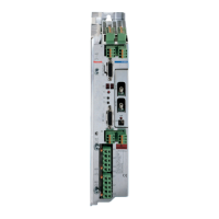
5.4 Front view
DC bus connection
Control voltage
H1 = LED - green:
Steady light: auxiliary bleeder functioning properly
Flashing light: DC bus < 50V
H2 = LED - red:
Steady light: Auxiliary bleeder overload, Bb contact open
S1 = Reset key
Ready to operate
X9 Plug-in screw terminal 0.2 to 4 mm², AWG 24-10,
rigid or flexible
X4: Plug-in screw terminal 0.2 to 2.5 mm², AWG 24-12,
rigid or flexible, flexible with or without ring terminals
F02DCC1P.fh5
1
2
3
4
+
+
-
-
1
2
3
free
+24 V
free
X4
X9
ECODRIVE
DIGITAL
AC-SERVO
BLEEDER
109-0963-3901-01
X9
L+1
L+2
L-1
L-2
X4
H1
H2
S1
RESET
4
5
6
0V
Bb
Bb
X4
Protective conductor connection
•
•
•
Fig. 5-6: Front view of the auxiliary bleeder module BZM01.1 with supply termi-
nals
LSA Control S.L. www.lsa-control.com comercial@lsa-control.com (+34) 960 62 43 01

 Loading...


