General instructions for assembly 25/32
RE 64276-01-R/10.2017, M4-12, Bosch Rexroth AG
5 General instructions for assembly
This section contains generally valid instructions for assembly, disassembly and
repair of the control block M4-12.
Detailed instructions for assembly, disassembly and repair can be found in the
following documents:
Table 21: Related documents
Document number
Assembly of the control block segments 64276-10-R
Repairing the valve 64276-20-R
Repairing the electro-proportional pressure relief 64276-30-R
Repairing the electronics EPM2 64276-40-R
Repairing the electronics CPM 64276-41-R
Repairing the inlet plate 64276-50-R
Repairing the inlet plate for safety-related applications 64276-51-R
5.1 Screw connection for hydraulic connections
• Pipe thread in accordance with ISO 2281
• Lightly grease the screw connection
5.2 Screw connection on the control block segment
• Torque wrench
1. Use the screw connection in accordance with section 5.1 “Screw connection for
hydraulic connections” on page20.
2. Screw the screw connection in clockwise.
3. Tighten the screw connection with a torque wrench in accordance with the
manufacturer’s instructions.
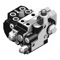
Fig. 11: Inlet plate Fig. 12: Inlet plate Fig. 13: Directional valve
Tools
Assembly
 Loading...