12/24 Assembly description
BoschRexrothAG, control block SB24/34, RE 66170-10-R/2019-05-15
5 Assembly description
The assembly / disassembly isdescribed using two dummy control blocks with
5block segments each asexample.
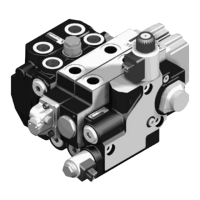
Table 5: Control block segments
Position Designation Abbreviation
Connecting plate AP
Directional valve EHR SVL
,
Directional valve SB SVL
End plate EP
End valve EVL
▲ Example with end plate ▲ Example with end valve
5.1 Control block assembly
5.1.1 Preparation ofthe block segments for the assembly
Prepare the flange surface O-ring side ofthe block segments asfollows:
1. Block segments with shuttle valve:
Assemble the shuttle valve according tochapter6.2 "Repairing the shuttle valve".
2. Block segments with shuttle valve with spring pre-tension:
Assemble the shuttle valve according tochapter6.3 "Repairing the spring
pre-tensioned shuttle valve".
3. Assemble the sealing elements according tochapter6.1 "Sealing elements for
control block segments".
 Loading...