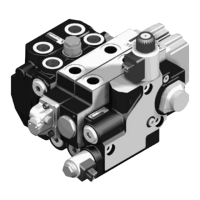
Removal of the SM 12 control block5.2
Install a vacuum pump on the tank to limit oil leakage when f
connections are removed.
After disconnecting the lines from the block, immediately fit the sealing f
plugs. Make sure to collect any possible oil leakage in a suitable
receptacle.
Unscrew the mounting screws and remove the control block. f
Installation of the SM 12 control block5.3
Contact faces must be perfectly clean. f
Check the evenness of support area on the machine (Tolerance: f
0.5 mm).
Check the condition of line connector seals. f
Clean the block if it has been in storage for a long period of time. f
Correctly place and secure the control block onto the machine with the f
mounting screws.
Connect the lines to the block as per the connecting diagram and f
tighten to the torque specification (refer to the table in the Data sheet).
Ensure that hoses are not twisted or rub. f
Once correctly installed, the unit can be placed into operation.
Starting, maximal pressure set up5.4
Decalibrate the primary pressure relief valve (17 mm open end spanner f
on counternut) before starting the machine,
Maintain one of the control block spool valve in action before the linked f
hydraulic receiver is at the end of stroke.
On the spool valve, the value of the secondary valve pressure must be
greater than that of the primary pressure relief valve to adjust.
Adjust the maximum pressure measured in M using the primary f
pressure relief valve (6 mm socket wrench).
Tighten the counternut of the adjusting screw to the torque: f
20 ± 10% N.m
.
RE 64122-S/06.2011 | Type SM 12 Bosch Rexroth AG 9/30
Removal / installation of the SM 12 control block
 Loading...