Wall Tamper Jumper
DATA
PWR
-
+
Wall Tamper disabled
(Default Position)
Wall Tamper enabled
Jumper left on pin for storage only.
Figure 3 - Wall Tamper Jumper
• Replace the Inside Cover.
• Place the Spring from the hardware packet over the shaft of the
Tamper Switch located on the back of the Receiver (see
Figure 4).
Rear of receiver
Figure 4 - Installing the Tamper Spring
NOTE:Gently press the Spring onto the tapered shaft. Do not force it
down onto the shaft.
3.3 Mounting the Receiver
• Determine the mounting location of the Receiver.
• If not already done, remove the Outer Cover from the Receiver (see
Figure 1) and set it aside.
• Place the Receiver base on the wall at the desired mounting location
and mark the two Mounting Holes (see Figure 5).
Antenna Connectors
Bus and
Power
Connector
Cover
Tamper
Switch
Mounting Holes
DATA
PWR
-
+
Figure 5 - Receiver with Outer Cover removed
• Drill holes and install anchors (supplied) if necessary.
• Secure the Receiver base to the wall with screws (supplied).
• Insert an Antenna into the outside terminal on two of the Antenna
Connectors as shown in Figure 6. Tighten screws to secure the
Antennas.
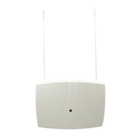
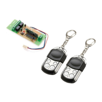
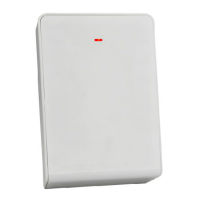
1.0 General Information
The RF3212E RF Receiver allows you to use wireless devices
when used with the EDM Solution Control/Communicator.
2.0 Specifications
• Dimensions (HxWxD): 10.8 cm x 15.2 cm x 3.0 cm
• Operating Temperature: 0°C to +65°C
• Frequency: 433.42 MHz
• Power Requirements: 12 VDC, 30 mA, nominal
• Compatible Control Panels: EDM Solution Ultima models
844, 862, 880
• Compliance: CE 0165 - This device complies
with EN 300683, EN 300220, and
89/336/EEC.
3.0 Mounting
3.1 Mounting Considerations
• The Receiver should be mounted in a central location in regard
to all wireless sensors, whenever possible.
• The Receiver should be mounted on a vertical surface with at
least 25 cm clearance for the antennas.
• Avoid mounting the Receiver in areas with significant metal or
electrical wiring; such as, furnace rooms and utility rooms. If this
is unavoidable, mount the Receiver with the antennas extending
above any metal surface.
• Avoid mounting the Receiver in areas where it may be exposed
to moisture.
• Reception distances are generally improved with higher
mounting locations and with no metal objects near the Antennas.
3.2 Wall Tamper Setup (Optional)
To enable the Wall Tamper Switch, follow the procedure below. If
the use of the Wall Tamper is not desired proceed to section 3.3.
• Remove the Outer Cover of the Receiver (see Figure 1) and set
it aside.
Insert screwdriver here
and press in
Figure 1 - Removing the Outer Cover
• Remove the Inside Cover (see Figure 2) by pressing the Latch.
Press Latch
to remove Inside Cover
Cover Tamper
DATA
PWR
-
+
Figure 2 - Removing the Inner Cover
• Move the Wall Tamper Jumper as shown in Figure 3.
Installation Instructions
for the
RF3212E RF Receiver