1 689 989 4582020-01-01 | Robert Bosch GmbH
Operation | VDI III | 15 en
The following steps are required if the pass-
word for a point-to-point connection is to be
reset.
1. Click the wireless-network icon in the
Windows taskbar.
A list of available wireless networks wi
-
thin range of the computer will be dis-
played.
2. Select "Open Network and Sharing Center."
3. Select "Manage Wireless Networks" from
the left column.
4. Select the "Change adapter" menu, and click
the diagnostic device in the list.
5. Remove the saved point-to-point network. Its
name will contain the sequence of charac
-
ters "MTS6531" and the last 8 digits of the
serial number of VDI III (MTS6531xxxxxxxx).
6. When you reconnect VDI III to the computer
using the USB connecting cable, a new pass
-
word will be created.
5.4.3 Reset to factory settings
Resetting VDI III to factory settings will also
reset the settings for the point-to-point connec
-
tion to the factory default. Any software upgra-
des that have been installed to VDI III will still
be installed. When the reset is finished, VCI
Manager will display the "VCI Explorer" tab.
All wireless-access-point configurations will be
lost.
1. Start the "VCI Manager" program.
2. Plug VDI III into an external 12V power
source.
3. Plug the USB connecting cable into the com-
puter and VDI III, and allow VDI III to boot
completely.
4. Establish a connection to VDI III in VCI
Manager.
5. Select the "Network setup" tab.
6. Click <Set factory default>.
" VDI III will be set to factory settings.
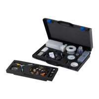
5.5 Connecting the diagnostic
device to a vehicle
The vehicle connection kit of VDI III contains
a diagnostic connection cable that connects
VDI III to the vehicle's DLC interface (SAE
J1962).
Refer to the wiring diagram for the vehicle to
be tested to determine the location of the DLC
connection on the vehicle.
1. Connect the 26-pin end of the diagnostic
connection cable to the top of VDI III, then
tighten the screws.
2. Connect the 16-pin end of the diagnostic
connection cable to the DLC connection of the
vehicle.
Connecting the diagnostic device to the power
supply
VDI III is powered by the vehicle's 12- or 24V
battery.
CAUTION – non-approved acces-
sories – malfunction
Risk of injury
¶ Non-Bosch cables are not
approved for use with this de
-
vice, including non-Bosch USB
connecting cables.
 Loading...