1 689 989 4582020-01-01 | Robert Bosch GmbH
Product description | VDI III | 9 en
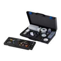
4.3 VDI III ports and control ele-
ments
VDI III has various buttons and standardized
ports for operating the device and connecting
it to the vehicle electrical system and workshop
network. These ports and buttons are shown in
the following illustrations.
DIAGNOSI
1
2
4
3
3
6
7
Item Description
1 LED status lights
2 Control buttons
3 2x USB-A port
4 Port for diagnostic connection cable
5 USB-B port
6 WLAN adapter
7 Ethernet port
4.4 Universal serial bus (USB) port
VDI III has a fixed USB configuration that can-
not be changed. This ensures that VDI III can
always establish a connection to a single com
-
puter running the "VCI Manager" software or
the user software so it is possible to configure
the LAN or WLAN settings required by the local
network. In addition, the USB connection is
required to configure the firmware on VDI III,
to pair the computer with VDI III and to update
the firmware.
4.5 Wireless local area network
(WLAN)
During setup and configuration of the WLAN
connection (802.11b/g/n), VDI III must be con
-
nected to a computer running the "VCIManag-
er" software and be paired with the computer
by USB.
4.6 Other properties of VDI III
4.6.1 Data transfer
The connection between VDI III and the vehicle
electronics is established via the 26-pin diag
-
nostic connection cable.
 Loading...