Assembly
W 120-5 O – 6 720 819 306 (2018/10)
27
5.2.1 Connecting the DHW cylinder on the water side
System schematics with all recommended valves ( Fig. 9, page 46).
▶ Use installation material that is heat-resistant to 160 °C (320 °F).
▶ Never use open, vented expansion vessels.
▶ Use metal connection fittings in potable water heating systems with
plastic lines.
▶ Size the drain line in accordance with the connection.
▶ To facilitate debris removal, never install elbows in the drain line.
▶ If using a non-return valve in the cold water supply: Install a pressure
relief valve between the non-return valve and cold water inlet.
▶ Install a pressure reducer if the static system pressure is in excess of
5 bar.
5.2.2 Installing a pressure relief valve (on site)
▶ Install a type-tested pressure relief valve on site that is approved for
potable water (DN 20) in the cold water supply ( Fig. 9,
page 46).
▶ Observe the pressure relief valve installation instructions.
▶ Terminate the discharge pipe of the pressure relief valve where it will
be easily visible in the frost-proof area via a dewatering point.
– The discharge pipe must be at least equal to the outlet cross-
section of the pressure relief valve.
– The discharge pipe must be able to discharge at least the flow rate
that is feasible at the cold water inlet ( Tab. 4, page 25).
▶ Attach a notice with the following text to the pressure relief valve:
"Never close the discharge pipe. During heating, water may be
discharged for operational reasons."
If the static system pressure exceeds 80 % of the pressure relief valve
excess pressure:
▶ Install a pressure reducer upstream ( Fig. 9, page 46).
5.3 Installing the hot water temperature sensor
Install the hot water temperature sensor at the test point [4] to measure
and monitor the DHW temperature in the DHW cylinder
( Fig. 3 page 45).
▶ Install the hot water temperature sensor ( Fig. 10, page 47).
Ensure that the sensor surface has contact with the sensor pocket
surface over its full length.
Item Description
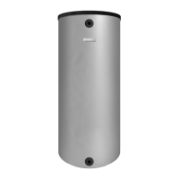
1 Storage cylinder
2 Air vent valve
3 Shut-off valve with drain valve
4 Pressure Relief Valve
5 Non-return valve
6 Stop valve
7 DHW circulation pump
8 Pressure reducer valve (if required)
9 Test valve
10 Non-return component
11 Pressure gauge connector
AB DHW outlet
EK Cold water inlet
EZ Circulation inlet
Table 7 System schematics ( Fig. 9, page 46)
Gas supply
pressure
(static
pressure)
Pressure relief
valve excess
pressure
Pressure reducer
in the EU outside the EU
< 4.8 bar 6 bar not required
5 bar 6 bar max. 4.8 bar
5 bar 8 bar not required
6 bar 8 bar max. 5.0 bar not required
7.8 bar 10 bar max. 5.0 bar not required
Table 8 Selection of a suitable pressure reducer
 Loading...