Pre-Installation
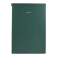
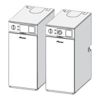
Greenstar Danesmoor External
ErP+
and External System
ErP+
6720821725 (2018/04)16
4.7 Boiler locations and clearances
Clearances:
▶ Minimum service and flue clearances.
– Above - 600mm
– Front - 600mm
– RH/LH clearance flue outlet on opposite side -10mm
– RH clearance flue outlet on rear - 45mm
– LH clearance flue outlet on rear - 85mm
– Rear clearance flue outlet on side - 50mm
– Rear clearance flue outlet on rear 2500mm
It is strongly recommended that the flue terminal faces away from
walls to reduce the possibility of wetting occurring.
Fig. 17 Above clearance
Fig. 18 Rear exit flue clearances
Fig. 19 Left exit flue clearances
Fig. 20 Right exit flue clearances
4.8 Flue terminal positions
WARNING: This appliance should not be installed where
there is a potential for excessive ground water coverage.
This boiler is only suitable for installing externally at a
suitable location onto a fixed permanent rigid surface
capable of supporting the boiler weight.
There must be a sufficient hard standing around the
appliance to allow for servicing.
The boiler must be installed on a flat level surface to
ensure that condensate does not enter the primary heat
exchanger.
Tarmac and wood hardstandings are not recommended.
6720809437-08.1Wo
600mm
2500mm
600mm
BASE
FRONT
600mm min
6720809437-09.1Wo
FRONT
2500mm
45mm
85mm
600mm
Plan
view
NOTICE:
▶ All measurements are the minimum clearances
required.
▶ Terminals must be positioned so to avoid
combustion products entering the building.
▶ Support the flue at approximately one metre
intervals and at a change of direction, use suitable
brackets and fittings:
- flue bracket 125mm x 1 - part no.: 7 716 191 179-
▶ In spite of the dimensions given here, the terminal
must not be closer than 300mm to combustible
material, 600mm in the case of a thatched roof.
▶ Terminals must be positioned so to avoid products
of combustion accumulating in stagnant pockets
around the building or entering the building.
▶ Terminals must be at least 1.8m from an oil storage
tank unless a wall with of at least 30 minutes fire
resistance and extending 300mm wider and higher
than the tank is between the tank and the terminal.
NOTICE:
▶ Installations in car ports are not recommended.
▶ Dimensions from a flue terminal to a fanned air inlet
to be determined by the ventilation equipment
manufacturer.
▶A flue terminal guard should be fitted over a terminal,
if persons could come into contact with the terminal,
or it could be subject to damage and where the
terminal is less than 2m from the finished floor level.
6720809437-10.1Wo
50mm
10mm
600mm
2500mm
FRONT
Plan
view
6720809437-11.1Wo
FRONT
2500mm
10mm
600mm
50mm
Plan
view

 Loading...


