Information about the appliance | 15
6 720 643 068 (2011/06)Copyright (optional information)
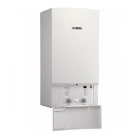
Key to Fig. 6:
1 Heatronic boiler control
2 ON/OFF switch
3 Burner flame indicator
4 Service button
5 Emissions test button
6 Boiler high limit dial
7 Mounting socket for outdoor reset controls
8 DHW thermostat
9 Key pad lock
10 ECO button
11 Reset button
12 Display
13 Condensate trap
14 Test ports for inlet gas pressure
15 Adjustment screw, minimum gas volume
16 DHW temperature sensor
17 Plate-type heat exchanger
18 Automatic air vent
19 Maximum gas adjuster
20 Flue gas temperature limiter
21 Combustion air intake
22 Supply pipe
23 Connection for optional low water cut off (LWCO)
24 Additional supply temperature limiter
25 Gas/air premix chamber
26 Expansion vessel
27 Fan
28 Bracket
29 Wall hanging bracket
30 Exhaust pipe
31 Sight glass
32 Set of electrodes
33 Supply temperature sensor
34 Boiler block temperature limiter
35 Inspection and cleanout cover
36 Condensate collector
37 Flow meter
38 3-way valve
39 Drain cock
40 Condensate drain hose
41 Boiler circulator
42 Pump speed switch
43 Pressure relief valve (heating zone)
44 Safety relief valve discharge hose
45 Boiler water pressure gauge

 Loading...


