4 • English EdgeMax EM90/EM180 • Installation Guide
PRO.BOSE.COM
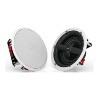
Setup
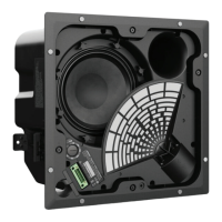
Installation Options
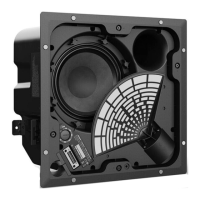
Installation Options and Accessories
q Adjustable Tile Bridge (included)
w Rough-in Pan (optional)
Conduit Fitting
If using a flexible metal conduit, use with a ⅜-inch conduit
fitting or a ⅜-inch dual (duplex) connector.
Note: Conduit fittings are not provided.
q
w
⅜-inch single in ⅜-inch duplex in/loop
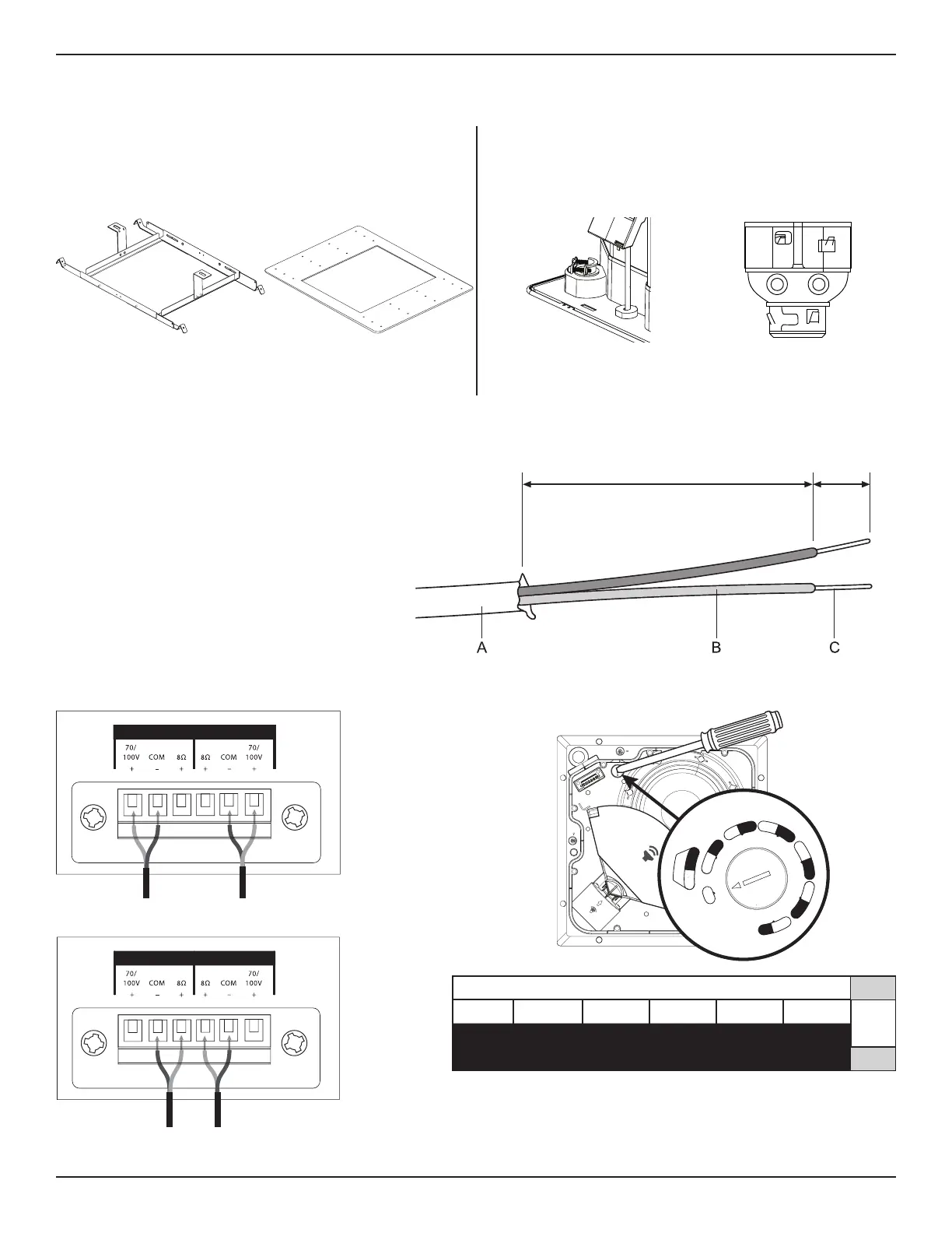
Wiring the Loudspeaker
With Use of Direct Input Terminals
Wire gauge requirements from loudspeaker line
wiring to loudspeaker terminals: Use 18AWG
(0.8mm
2
) to 14AWG (2.5 mm
2
) size wire only.
Preparing the Wire
Trim back the outer jacket (A) and some of the
wire insulation (B) to expose enough bare wire
(C) to attach to the terminals.
69.9 mm
2.75 in
6.4 mm
0.25 in
Loudspeaker SettingsConnection Diagrams
70V/100V
8
IN OUT
IN OUT
AUDIENCE
REMOVE AFTER PRODUCT INSTALLATION
WALL
1
0
W
2
0
W
5
W
1
0
W
8
0
W
N
C
8
Ω
2
.
5
W
5
W
4
0
W
8
0
W
2
0
W
4
0
W
7
0
W
1
0
0
W
I
N
P
U
T
70V
2.5W* 5W 10W 20W 40W 80W
8Ώ
5W* 10W 20W 40W 80W NC**
100V
** NC: No Connection (do not use)
* Factory default
Transformer Tap Setting
Set tap by turning. Use a flat head screwdriver.
 Loading...