30
DISASSEMBLY PROCEDURE
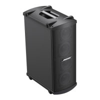
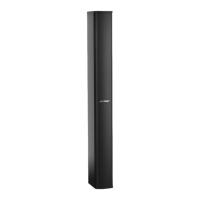
5.4 Figure 10 shows the opposite side of the
driver assembly.
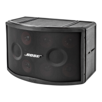
5.5 Carefully assert the pulling direction towards
the mid section as shown in Figure 11.
CAUTION: The left and right driver assembly is
attached together with one internal screw located
underneath the center section of the driver
assembly. The driver assembly can break apart
and is not repairable if care in removal is not
taken.
5.6 Figure 12 shows the driver assembly wire
harness connectors. Disconnect the wire harness
connectors from the Interconnect PCB assembly.
Note: Observe the position and screw locations of
the interconnect PCB during disassembly.
6. Interconnect PCB Removal.
6.1 Perform procedure 5 to remove the driver
assembly.
6.2 Remove the seven screws as shown in
Figure 13 that secure the Interconnect PCB to the
MSA12X housing.
Figure 10
Figure 11
Figure 12
Figure 13
 Loading...