29
DISASSEMBLY PROCEDURE
1. Bottom Cover Removal
1.1 Remove the 6 screws indicated in Figure 3.
1.2 Lift off the bottom cover.
2. I/O PCB Removal
2.1 Perform procedure 1 rst.
2.2 Remove the FFC from connector J606.
Figure 4.
2.3 Remove the four screws securing the I/O
PCB. Figure 4.
2.4 Lift up the I/O PCB and disconnect the
cable harness from J610. Figure 5
2.5 Disconnect the FFC from J607. Figure 5
2.6 Press on J605’s two connector release tabs
and carefully pull out the FFC. Figure 5.
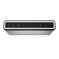
3. Side Panel Removal
3.1 Perform procedure 1 rst.
3.2 Grasp the side panel and slide it upward
to remove the side panel from the enclosure.
Figure 6.
Figure 3. Bottom Cover
Figure 4. I/O PCB
Figure 5. I/O PCB - Cables
Figure 6. Side Panel
 Loading...