33
ASSEMBLY KEY POINTS
1. Replacing Drivers
1.1 Loop the driver harness through the bafe
and the enclosure as shown in Figure 19.
1.2 Connect the driver harnesses to the amp/
power supply PCB.
1.3 Secure the drivers and bafe with the
screws removed in disassembly procedure 4.
The driver’s lower inner screws drives into the
metal bafe and are different than the other
14 screws that drive into the plastic enclosure.
These two screws have a machine thread -
item 20 in the Main Part list. Figure 20.
Note: If the bafe gasket peeled away from the
bafe, replace with a new bafe to prevent air
leaks. Item 26 in the main part list.
2. FFC Dressing
2.1 Before securing the I/O PCB or Wi-Fi
module, connect the FFCs to ensure they are
fully inserted. It is difcult to connect the FFCs
when the PCB is secured in place.
2.2 The FFC connecting the top connector on
the I/O PCB (J606) to the top connector on the
Wi-Fi module (J1203) should lay on top of the
other FFC running between the two PCBs and
over the bafe.
2.3 When properly dressed, the two cables
should have a crossing pattern as shown in
Figure 21. Failure to properly dress these
cables will cause stress on the connections
resulting in a intermittent connection.
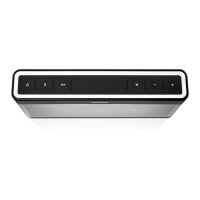
3. Button Replacement
3.1 Align the replacement button pad to the
alignment features in the top cover.
3.2 Remove the adhesive backing and align
the button PCB over the button pad and the
top cover alignment features. The button PCB
connector will be opposite the grille. Figure 22.
3.3 Secure the button PCB with the screws
removed in disassembly procedure 5.
Figure 19. Driver Harness Dressing
Figure 20. Driver Lower Inner Screws Location
Inner Screws - Machine Thread
Figure 21. FFC Dressing
Figure 22. Button Pad
 Loading...