5-11
Electrical Systems Section 5
Helm Station Switch Panel
Main DC circuit 3 of 6 provides power to the helm
station switch panel. The bilge pump switch is not
included in this circuit.
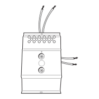
This circuit is protected by one 60-amp, push button
breaker. The 60-amp breaker is located inside the
console within seven inches of the electronics OFF-
ON battery switch.
One Group 27 105 amp hour, deep cycle battery
(optional) powers this circuit through the electronics
battery switch. A two-battery system will have one
electronics OFF-ON battery switch.
The helm station switch panel has no connection to
the negative side of the DC electrical system. Any
accessories installed on these switches must also
connect to the negative side of the DC electrical sys-
tem through the negative terminal strip provided. One
negative terminal strip is located in the console.
See Electrical Diagram for wire color codes.
! CAUTION
The total combined amperage ratings for all
accessories connected to the helm station
switch panel must not exceed 60 amps. Over-
loading the helm station switch panel might
cause repeated tripping of the 60-amp breaker
and other electrical problems.
 Loading...