2 PC 1106 - PC 1112
III - PRESENTATION III - PRESENTATION
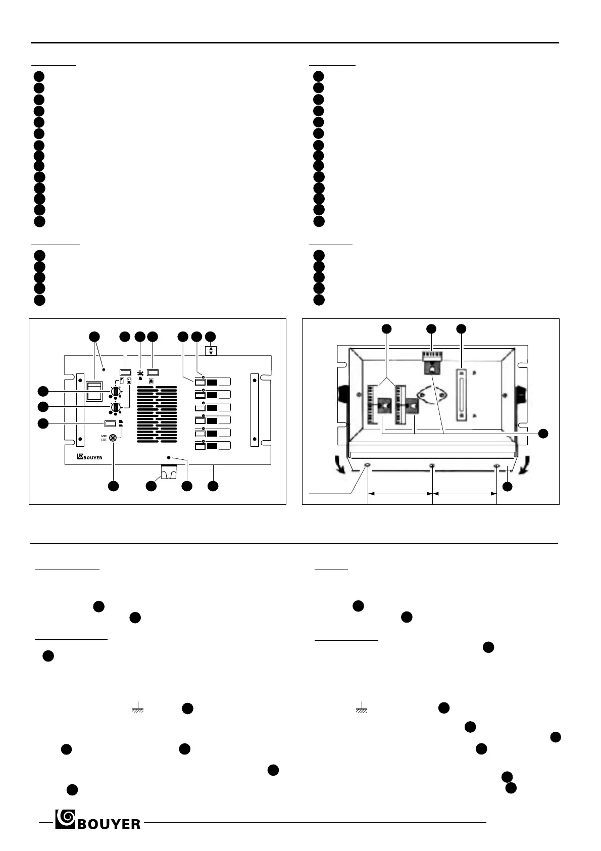
Face avant (Fig. I)
1 Interrupteur Marche/Arrêt et voyant lumineux
2 Touche “Parole / Ecoute”
Réglage de niveau de sonnerie( par tournevis)
Bouton d’appel par sonnerie
Touches de prise de ligne (6 ou 12)
3 Voyants d’appel ( 6 ou 12)
4 Etiquettes d’identification de lignes
5 Orifices pour dégagement des étiquettes
6 Vis de fixation du support microphone
Support de microphone amovible
Jack (6,35 mm) du microphone extérieur
7 Mise en service du microphone "paume de main"
Réglage de volume “Parole”
Réglage de volume “Ecoute”
Face arrière (Fig. II)
15 Connecteurs postes secondaires
Connecteur alimentation et microphone
16 Serre-câbles
Verrouillage des connecteurs
18 Bride de fixation
Front panel (Fig. I)
ON/OFF switch with indicator lamp
Talk/listen button
Tone volume control (by screwdriver)
Tone call button
Channel selectors (6 or 12)
Incomming call indicator lamps (6 or 12)
Channel identification labels
Label removal slots
Fixing screw for microphone support
Detachable microphone support
Jack socket (6,35 mm) for external microphone
Fist microphone switch
Speech volume control
Listen volume control
Rear panel (Fig. II)
15 Substation line connectors
Microphone and power supply connector
Cable grip
Connector retaining clips
18 Fixing bracket
1
2
10
11
12
13
14
3
4
5
6
7
8
9
1
ON
1
2
3
4
5
6
PC 1106
2 43 5 76
89
1011
12
13
14
15 16 17
18
19
100 mm 100 mm
3 trous Ø 5,2 mm
IV - INSTALLATION IV - INSTALLATION
• MISE EN PLACE
Le coffret peut être soit encastré (Fig.III), soit fixé avec la
fourche orientable (Fig. II).
Les PC 1106 et PC 1112 sont livrés avec un support de
microphone qui peut, au choix, être fixé sur une paroi ou
sur l'appareil par la vis (Fig.I).
• BRANCHEMENTS
Desserrer d’un demi-tour les vis sur les pièces de maintien
(Fig. II) et dégager les connecteurs.
Relier chaque poste secondaire à une des paires de plots du
bornier, numérotées de L1 à L12 (Fig. II). Voir section des fils
préconisés (Tableau Fig. V)
Si l’environnement est fortement parasité, utiliser un câble
blindé, blindage relié à , bornier .
L’alimentation continue (12V à 48V) est raccordée aux
bornes + et - indiquées sur la batterie (Fig. IV).
Le microphone peut être branché en face avant sur la prise
jack 9 ou à l' arrière sur le bornier (Fig. IV).
Replacer les connecteurs conformément au repérage des éti-
quettes puis les immobiliser avec les pièces de maintien 19
Afin d'éviter l’arrachement des fils, les maintenir avec le serre-
câble .
• FITTING
The unit may be either flush mounted or fixed by its tilting
bracket (Fig. II and Fig. III).
The PC 1106 and PC 1112 are supplied with a microphone
support 11 which can either be crewed to a board or fixed to
the unit using screw 12 (Fig.I).
• CONNECTIONS
Loosen the connector retaining clip screws 19 (Fig. II)
by half a
turn and remove the connectors.
Connect each substation to one of the pairs of
terminals numbe-
red L1 to L12 (Fig. II). See recommended cable diameters
(Fig.V).
In interference is likely use screened cable connecting the
screen to on terminal strip .
The DC power supply (12 V to 48 V) is connected to the + and
- terminals indicated on terminal strip 15 .
The microphone can be connected either to the jack socket 9
on the front panel or on terminal strip on the rear panel
(Fig.
IV).
Replace the connectors as indicated on the labels and then
secure them using the connector retaining clip 19 . In order to
avoid tugging the cable, secure using cable grip 17 .
15
16
17
18
19
11
9
10
16
16
17
18
18
Fig. I
Fig. II
1
2
10
11
12
13
14
3
4
5
6
7
8
9
15
16
17
18
19
11
9
10
16
16
16
17
18
18
 Loading...