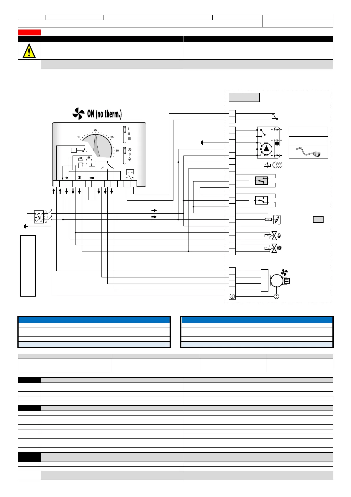
Schema elettrico Regolatore/Unità
Controller/Unit wiring diagram
Fan-coils, Slim terminal units, Medium terminal units, Aerotherms, Air barriers, etc.
CR22-010
SPE.: CR22
YV1-230V + YV2-230V + MS1-2+3P230 + TB.A1 + TB.W1 + ION + PUMP + SND-A
REF.: N°1 MOTORE AC (ASINCRONO) 230Vac~ 3-Velocità NO.1 AC MOTOR (ASYNCRONOUS) 230Vac~ 3-Speed
Tenere presente che modifiche elettriche, meccaniche e manomissioni in
genere fanno decadere la garanzia !!
ATTENZIONE: Effettuare correttamente i collegamenti elettrici
Un errato collegamento elettr. provoca la bruciatura dei dispositivi elettrici dell’unitá !
Please do not forget that warranty cannot be applied in case of electric,
mechanical and other general modifications !!
ATTENTION: Carry out correctly the electrical connections
A wrong electrical connection causes the burning of the unit electrical equipments !
X1
Morsettiera per collegamento a comando remoto
(Fornita montata sull’unità; Dipende dall’articolo richiesto/ordinato)
Terminal board for connection with the remote control
(Supplied mounted on the unit; Depending on the requested/ordered article)
X1= (MRS1= Morsettiera tipo “Mamut” IP20); (MRS2=MRS1+TM); (MRS3=MRS1 con coperchio di chiusura IP40);
(MRS4=MRS3+TM); (MRS5=MRS1 dentro scatola elettrica IP55); (MRS6=MRS5+TM).
Standard sono presenti solo i morsetti occupati (PE,1,2…). I morsetti 5,6…n sono presenti solo se installati i relativi
accessori. In alcuni casi i morsetti non occupati possono non essere presenti: in questi casi mancano i morsetti non
occupati (es. 5-6 se non presente TM) mentre i morsetti successivi mantengono la stessa numerazione (es. il 7 rimane 7).
X1= (MRS1=“Mammoth” type terminal board IP20); (MRS2=MRS1+TM); (MRS3=MRS1 with closing cover IP40); (MRS4=MRS3+TM);
(MRS5=MRS1 inside IP55 electrical box); (MRS6=MRS5+TM).
Standards there are only employed terminals (PE, 1.2 ...). The terminals 5,6 ... n are present only if related accessories are
installed. In some cases not employed terminals can also not be present: in these cases not employed terminals are missing (eg.
5-6 if not present TM) while following terminals maintain same numbering (eg. 7 remains 7).
NOTE NOTE
PER ULTERIORI INFORMAZIONI, PREGO RIFERIRSI ALLA SCHEDA TECNICA DEL MOTORE SERRANDA
FOR FURTHER INFORMATIONS, PLEASE REFER TO THE THECHICAL SHEET OF THE MOTOR AIR LOUVER
PER LE UNITÀ PROVVISTE DI IONIZZATORE “ION” : PER LA SICUREZZA È OBBLIGATORIO
REALIZZARE UNA EFFICIENTE MESSA A TERRA DELL’INTERA STRUTTURA METALLICA !!!
FOR THE UNIT PROVIDED WITH IONIZER “ION”: FOR SECURITY REASON IT’S COMPULSORY
TO REALIZE AN EFFICIENT GROUNDING OF THE ENTIRE METALLIC STRUCTURE !!!
PER ULTERIORI INFORMAZIONI, PREGO RIFERIRSI ALLA SCHEDA TECNICA DELLA POMPA FOR FURTHER INFORMATIONS, PLEASE REFER TO THE THECHICAL SHEET OF THE PUMP
OBBLIGATORIO RIFERIRSI AL MANUALE DEL REGOLATORE
MANDATORY REFERED TO MANUAL OF THE CONTROLLER
Vedi prescrizioni riportate sugli schemi elettrici degli accessori
See the instructions specified in the wiring diagrams of the accessories
Riferimenti - References Colori cavi – Wires colours Colori cavi – Wires colours Colori cavi – Wires colours
L
GNYE
BK
GY
N
BN
RD
VT
PE
BU
WH
OG
1,2...; a,b…; etc.: Sigle presenti sulle morsettiere e sui dispositivi elettrici - Marks on the terminal board and on the electrical equipments
COMPONENTI STANDARD FORNITI MONTATI
STANDARD EQUIPMENTS SUPPLIED MOUNTED
MV
Motore ventilatore asincrono 230Vac (AC)
Com/Min/Med/Max = Comune, Velocità Min/Med/Max del ventilatore
230Vac Asynchronous fan motor (AC)
Com/Min/Med/Max = Common, Min/Med/Max fan speed (Low, Medium, High)
C
Condensatore (possibili differenti cablaggi a seconda del modello)
Capacitor (possible different wiring depending on the model)
X1
Morsettiera elettrica dell’unità (con terminali lato utente)
Electrical terminal board of the unit (
X2
Eventuale dispositivo intermedio (es.: Connettore, Autotrasformatore, ecc.)
Possible intermediate equipment (ex.: Connector, Autotransformer, etc.)
ACCESSORI (presenti solo se richiesti/ordinati)
ACCESSORIES (installed only if requested/ordered)
YV1-230V
Valvola batteria principale 230V on/off (4Tubi= freddo)
YV2-230V
Valvola batteria addizionale
MS1-2+3P230
otore serranda aria esterna (rinnovo) 2&3
Punti, alimentazione 230Vac, senza ritorno a molla
Points motor external air louver (renewed), power supply 230Vac, without spring return
TB.A1
Termostato a bulbo antigelo lato aria
Air side Antifreezing bulb thermostat (for all units : 2
TB.W1
Termostato a bulbo antigelo lato acqua
Water side Antifreezing bulb thermostat
ION
PUMP
Pompa condensa con contatto allarme
(Tipo/Portata contatto: riferirsi al manuale della pompa)
Condensate pump with alarm switch
(Contact type/rating: please refer to the pump’s manual)
SND-A
COMPONENTI NON FORNITI (A CURA DEL CLIENTE);
(opp. Componenti forniti non montati (accessori forniti solo se richiesti/ordinati))
EQUIPMENTS NOT SUPPLIED (BY THE CUSTOMER);
(or equipments supplied not mounted (accessories supplied only if requested/ordered))
CR
Comando remoto (Regolatore)
IG-2p
Interruttore generale magnetotermico differenziale (230Vac, 2 contatti: Fase, Neutro)
differential switch (230Vac,
2 contacts: Phase, Neutral)
Note
I componenti dell’impianto elettrico (IG-2P, ecc.) devono essere scelti in funzione
dell’assorbimento elettrico dell’unità (o della sezione/componente) da alimentare.
The equipments of the electrical system (IG-2P, etc.) must be selected on the basis of
the electrical power consumption of the unit (or section/component) to be fed.
L
N
3
4
5
6
7
8
9
10
11
12
ax
in
13
S.A.
TM
T
N
L
PE
~
50Hz
YV1-230V
YV1-230V
YV2-230V
YV2-230V
Com
PE
Max
Med
Min
Com
PE
GNYE
Max
Med
Min
C
MV
X2
3
2
1
4
IG-2P
Alimentazione elettrica - Power supply
230Vac–1Ph–50Hz
YV1-230V
YV2-230V
9
8
7
10
BN
BU
BN
BU
BU
BN
ION
52
51
ION
ION
MS1 (N)
MS1 (230V)
MS1 (230V on/off)
TB.A1
TB.A1
TB.A1
TB.W1
TB.W1
TB.W1
33
32
31
34
35
36
Tae > T.set
Tae < T.set
C*
1*
2*
TB.A1
Com
Aria-Air
Tw > T.set
Tw < T.set
C*
1*
2*
TB.W1
Com
Acqua-Water
Rif. termostato IMIT
Ref. IMIT thermostat
Rif. termostato IMIT
Ref. IMIT thermostat
L
N
23
22
21
N°1
MS1-2+3P230
comune-common
chiude-closes
apre-open
senza (PE)
NO 83
Note: for the “PUMP” mod.
without (PE)
NO 83
PUMP (L)
PUMP (N)
BN
BU
GNYE
PE
N
L
PUMP
Alarm
Work
NOTA:
con cavo e spina
No “X1”
NOTE:
for the “PUMP” mod. with
cable and plug
No “X1”
84
85
81
82
83
PUMP (PE)
Dispositivi a corredo dell’unitá
Equipments included on the unit
UNIT
X1
SND-A
SND-A
92
91
BN
BU
SND-A
 Loading...