11
Hang up the handset ⑥ again, and continue, repeating the
same operations for the other receivers.
Exiting programming ⑦.
Briey press the PROG key on the power supplier: the PROG
LEDs and the entry panels LEDs will turn o.
NOTE. If no action is performed, the procedure will auto-
matically end after 30 minutes.
Programming in systems with entry panel with
numeric keypad M
Entering "programming" mode.
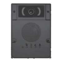
Press the PROG key on the power supplier ① until the PROG
LED turns on. The entry panel LEDs turn on as shown in gure
②.
NOTE. If the PROG LED turns off suddenly, this indicates
a malfunction in the connection between the power
supplier and the entry panel. Check the connections and
return to programming.
Wait 5 seconds for the autotest to nish.
Repeat the operation ③ a second time. Check that the entry
panel conguration is as illustrated in gure ④.
Programming the call codes.
Lift the handset (if present) of the receiver that you want to
programme ⑤ then press the door lock release and
AUX2 buttons ⑥. Enter the call code for the group (1 to
99) and then press the ⑦ key to associate the call code
with the receiver.
Hang up the handset ⑧ again, if necessary and continue,
repeating the same operations for the other receivers.
Exiting "programming" mode ⑨.
Briey press the PROG key on the power supplier: the PROG
LED and entry panel LEDs will turn o.
NOTE. If no action is performed, the procedure will auto-
matically end after 30 minutes.
Assigning codes and/or Tags to a button (group) N
Entering "programming" mode.
Position the RFID PROG jumper of the power supplier to posi-
tion “+” a; the PROG LED of the power supplier and the LEDs
and on the entry panel will ash slowly b.
NOTE. If the PROG LED turns off suddenly, this indicates
a malfunction in the connection between the power
supplier and the entry panel. Check the connections and
return to programming.
Badge
Move a badge/tag near any entry panel reader that has al-
ready been addressed and, after the conrmation tone, press
the key (group) to which the code should be assigned b.
If the maximum permitted number is exceeded (5) for each
group, an error tone will be generated.
Codes
Press , enter the access code (4-8 digits) followed by the
key on the keypad of any already addressed entry panel read-
er and, after the conrmation beep, enter the call code
for the group and then press (or press the group key).
If the maximum permitted number is exceeded (5) for each
group, an error tone will be generated.
Exiting programming. ⑤.
At the end, return the RFID PROG jumper to its standby po-
sition.
NOTE: the procedure will NOT end automatically!
Code and/or Tag deletion O
Entering "programming" mode.
Position the RFID PROG jumper of the power supplier to posi-
tion “-” a; the PROG LED of the power supplier and the LEDs
and on the entry panel will ash slowly b.
NOTE. If the PROG LED turns off suddenly, this indicates
a malfunction in the connection between the power
supplier and the entry panel. Check the connections and
return to programming.
Deletion of badges associated to a call group using
badge
Approach a badge/tag to the reader of any already addressed
entry panel; after the conrmation beep, approach the
badge/tag again b; by doing this all the badges associated
to the call group will be deleted.
Deletion of badges associated to a call group using
badge
Press enter the access code (4-8 digits) followed by the
key on the keypad of any already addressed entry panel read-
er ; after the conrmation beep, enter the access code (4-8
digits) again, followed by the key; by doing this all the
codes associated to the group will be deleted.
Deletion of badges and codes associated to a call group
using buttons
Press the call key ⑤ relating to the GROUP whose codes you
want to delete, for at least 10 seconds, after the beep briey
press the button again ; by doing this all the badges and
codes associated to the call group will be deleted.
Deletion of codes associated to a call group using key-
pad
Enter the call code followed by the key relative to the
GROUP for which you want to cancel the codes and, after the
beep, enter the call code again followed by the key .
This will delete ALL the codes assigned to the GROUP.
Exiting programming ⑨.
At the end, return the RFID PROG jumper to its standby po-
sition.
NOTE: the procedure will NOT end automatically!
Adjustment of visual eld of the entry panel's
surveillance camera S
When the system is in "programming" mode, (if necessary)
it is possible to adjust the surveillance camera's visual eld
from any receiver.
With the handset lifted (if there is one), by pressing the
"Self-connection ” ① key, you can scroll through the
10 possible congurations ② using the AUX1 or AUX2
keys ③. To adjust the "visual eld" of the other surveillance
cameras (if present), press the “Self-connection ” button
again.
The setting is saved automatically by exiting "programming"
mode.
Should it be necessary to make changes to a system
that's already been programmed (add, replace or remove
an entry panel) it will be necessary to go back into "pro-
gramming" mode to make the system acquire the chang-
es made.
Use of entry panels powered by VAS/100.30
Connection examples P Q
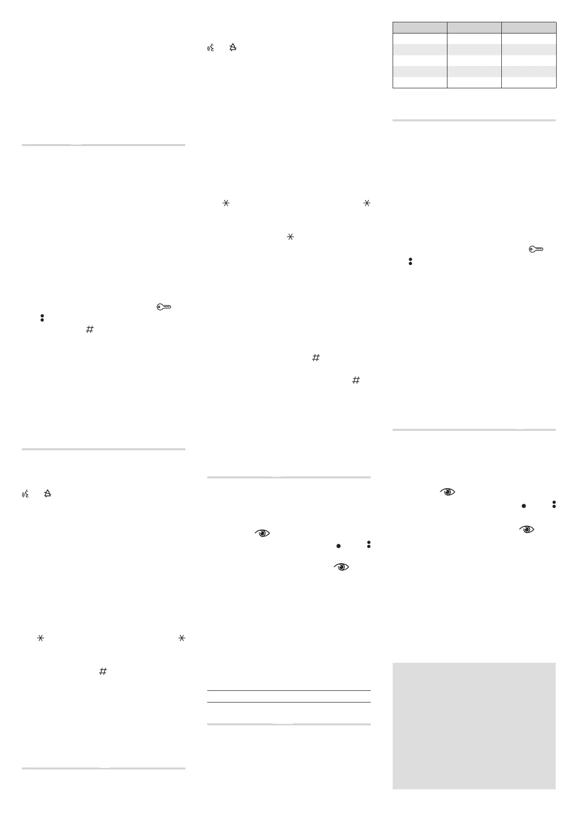
A maximum of 11 VZS/308C (5÷92 calls) can be connected to
the DMVC/01 or DMC/01 module Q①.
Cabling diagram for PUSH BUTTON connector ②
Reference Colour Meaning
C Black Common
1 Brown Call 1
2 Red Call 2
3 Orange Call 3
4 Yellow Call 4
Initial programming or reprogramming R
Entering "programming" mode.
Hold down the PROG button ① for at least 3 seconds and
release it within 6 seconds; the PROG LED comes on. The entry
panel LEDs turn on as shown in gure ②.
NOTE: Failure of the PROG LED to light up indicates a mal-
function. Check the connections and return to program-
ming.
Programming the call keys.
Lift the handset (if present) of the receiver that you want to
programme ③ then press the door lock release and
AUX2 ④ buttons. On the entry panel, press the call key to
be associated with the receiver ⑤: an acoustic signal will
conrm that the setting was stored. Hang up the handset ⑥
again, and continue, repeating the same operations for the
other receivers.
Exiting programming ⑦.
Briey press the PROG key; the PROG LED and the entry pan-
els' LEDS will turn o.
NOTE. If no action is performed, the procedure will auto-
matically end after 30 minutes.
Adjustment of visual eld
of the entry panel's surveillance camera S
When the system is in "programming" mode, (if necessary)
it is possible to adjust the surveillance camera's visual eld
from any receiver.
With the handset lifted (if there is one), by pressing the
"Self-connection ” ① key, you can scroll through the
10 possible congurations ② using the AUX1 or AUX2
keys ③. To adjust the "visual eld" of the other surveillance
cameras (if present), press the “Self-connection ” button
again.
The setting is saved automatically by exiting "programming"
mode.
Should it be necessary to make changes to a system
that's already been programmed (add, replace or remove
an entry panel) it will be necessary to go back into "pro-
gramming" mode to make the system acquire the chang-
es made.
DISPOSAL
Do not litter the environment with packaging material:
make sure it is disposed of according to the regulations in
force in the country where the product is to be used.
When the equipment reaches the end of its life cycle, avoid
discarding it within the environment.
The equipment must be disposed of in compliance with
current regulations, recycling its component parts wherever
possible.
Components that qualify as recyclable waste feature the
relevant symbol and material acronym.
 Loading...