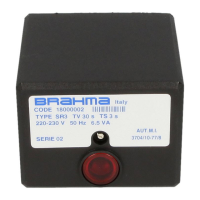
SR3 - VE3 - BV3 - GV2
CONTROL BOXES
CONTROL BOXES FOR FORCED
DRAUGHT GAS BURNERS, WITH
POWER UP TO 120KW.
DESCRIPTION
The SR3 - VE3 - BV3 - GV2 safety devices are suitable to
control forced draught gas burners for civil and industrial
applications.
The BV3 control is used for fast boilers in which hot water
(or steam) taking has to occur within short times, which
cannot be granted by using the SR3 and VE3 devices.
The GV2 control box is used for small boilers in which a
longer safety time is generally allowed.
According to TÜV Bayern, Monaco, the SR3 control is in
compliance with the German regulation DIN 4788, part 3,
for power up to 120KW. It also obtained the DIN-DVGW
89.11fBN approval, now expired and not renewable.
The “Laboratorio di Macchine e Termotecnica del Centro
Studi ed Esperienze” in Rome, Capannelle, tested the SR3
control for power up to 93KW, which obtained the
certification no. 3704/81/77/3A and the approval of the
Ministry of the Interior for fire prevention (circulars no. 68
and no. 42).
TECHNICAL DATA:
Supply voltage: 220V(-15% +10%)
50Hz (±5%)
on request: 110V
Operating temperature range: -10°C +60°C
Protection degree: IP40
Starting power consumption: 10VA
Operating power consumption: 6,5VA
Max. current rating I max.
- burner motor: 4 A
- EV valve: 2 A
- ignition transformer: 2 A
- alarm: 1 A
Regulators (T, PA, PG): 6 A
Times:
- prepurge time (TV):
SR3 - VE3: 50 s
BV3 - GV2: 20 s
- safety time (TS): GV2: 15 s
SR3 - VE3 - BV3: 3 s
- dropout time on running
flame failure: <1 s
Flame control:
- minimum ionization current: 0,5µA
- recommended ionization current: 7µA
- minimum insulation resistance between
probe, cable and ground: > 50MΩ
- voltage on the detection probe: 300V
Weight including socket: 550 g
FLAME CONTROL
A transformer having one primary and two secondary
windings supplies the electronic flame detection circuit at
low voltage, and the detection probe with about 300V. This
supply system offers the big advantage of having constant
ionization values, even if the network is a live-live
installation.
To check the efficiency of the flame detection circuit, you
have to proceed as follows: connect a low impedance
ammeter, as shown in Fig.1; the R1 ... Rn resistors in
series must give the total resistance value of 200MΩ (e.g.
20 resistors of 10MΩ 1/4W 5%). If the control box is
supplied with 220V, the measured current value is about
0,5+0,6µA DC, which causes the flame relay to switch on.
Lower current values indicate that the circuit is damaged or
only partially efficient.
4009_r00