8
Series 70 Electric Actuator
Installation, Operation and Maintenance Manual
NOTICE
Cam locking screw must be slackened before cam
adjustments and re-tightened after cam adjustments.
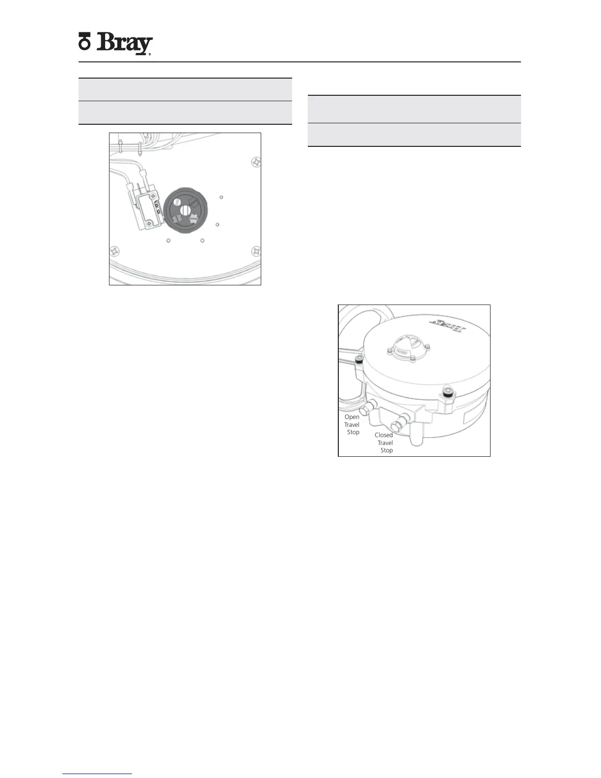
Figure 8. Top view of the indicator shaft.
NOTE: It is possible that the rotation of one cam will
move the other cam. If this occurs, hold the other knobs
or cams during adjustment.
4. Rotate the red cam adjustment knob by hand or
with a flat head screwdriver until the red cam lobe
just activates (depresses) the ‘closed’ switch from a
clockwise direction.
NOTE: If fixed auxiliary switches are installed, the auxiliary
cam will activate prior to the main cam.
5. Tighten the cam locking screw.
6. Manually operate the actuator counterclockwise until
the valve reaches the desired ‘open’ position.
7. Loosen the cam locking screw.
8. Rotate the green cam adjustment knob until the green
cam lobe activates (depresses) the ‘open’ switch from
a counterclockwise direction.
9. Tighten the cam locking screw.
10. Place the indicator rotor back on the indicator shaft.
Setting Mechanical Travel Stops
NOTICE
If the unit came assembled to a valve, the stops have
been factory-set and DO NOT need adjustment.
Mechanical travel stops are designed to prevent over
travel while manually operating the actuator. They are
not designed to stop the electric motor.
Mechanical travel stops are located outside of the
actuator base for easy readjustment. Stainless steel lock
nuts with O-ring seals hold the travel stops securely in
place. Travel stop spacers are used to ensure that travel
stop bolts are not engaged to where they could limit 0°
to 90° electrical operation.
NOTE: Actuator Size 130, 180 does not use travel stop
spacers.
Open
Travel
Stop
Closed
Travel
Stop
Figure 9. Mechanical Travel Stops (CW Close).
Follow the steps below to set the mechanical travels
stops.
1. Manually drive the actuator to the ‘closed’ position.
2. Once the actuator is in the ‘closed’ position, rotate
the handwheel clockwise:
• ½ turn for Actuator Size 003, 006.
• 1 turn for Actuator Size 008, 012, 020.
• ½ turn for Actuator Size 030, 050, 065.
• 2 turns for Actuator Size 130, 180.
3. Adjust the ‘closed’ travel stop bolt until the travel
stop spacer is fully engaged or the travel stop bolt
contacts the output segment gear.
 Loading...