16
Series 70 Electric Actuator
Installation, Operation and Maintenance Manual
Indication of Remote Control
Bray offers two field or factory installable kits to indicate
if a process controller has remote control of the Series
70 actuator. Remote control of the actuator can be
interrupted if the actuator handwheel has been left
engaged or if a local control station has been switched
out of remote mode.
A dry contact (voltage free) mechanical switch provides
indication if the handwheel is engaged. Alternatively, an
additional dry contact (voltage free) mechanical switch
can be placed in Local Control Station to provided
indication if the local control station is switched out
of remote mode. Both kits can be installed and wired
in series to provide dual indication. Dual indication
wiring is meant to indicate that remote control has
been interrupted and does not distinguish between
modes of interruption.
NOTE:
• Factory will need wiring diagram drawing
number and model of the existing unit if it is to
be retrofitted with a Remote Control Indication
kit. New wiring diagram will be provided based
upon this information.
• Some configurations may limit use of remote
control indication kits receptacles due to number
of wires entering through the conduit.
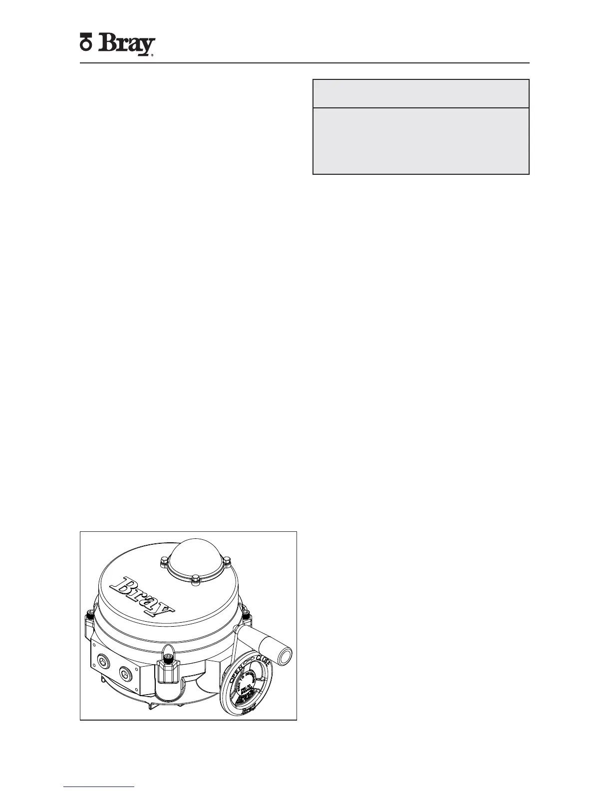
Spinner
A spinner is field or factory installable attachment to
the actuator handwheel to ease and speed the manual
operation of the Series 70 actuator. Actuator Size 003,
006 units mount the spinner on a lever which screws
onto the back of the handwheel. Actuator Size 008 - 180
units mount the spinner on the rim of the handwheel.
Figure 19. S70 with Handwheel Spinner Attached.
NOTICE
Care should be exercised in the use of a spinner
equipped handwheel.
Rapid operation of the handwheel to close the valve
may cause water hammer.
Rapid travel into a travel stop may cause damage.
Spinner Kit, Actuator Size 003, 006:
• Spinner and Lever Assembly
• #10-32UNF x 3/8” Flat Head Socket Cap.
Spinner Kit, Actuator Size 008 - 180:
• Spinner Handle
• ¼”-20UNC x ¾” Socket Head Shoulder Bolt
Tools Required:
• Hex Key, 1/8” (Actuator Size 003, 006)
• Hex Key, 3/16” (Actuator Sizes 008 - 180)
Installation Procedure:
• For Actuator Size 003, 006 – Position the lever onto
the back of the handwheel then screw the flat head
cap screw in to place from behind.
• For Actuator Size 008, 012, 020-180 – Place the
socket head shoulder bolt through the spinner
handle and screw it firmly into the handwheel rim.
Receptacles (Quick Connectors)
Bray offers plug-in receptacles as a field or factory
option for quick and easy field wiring of Series 70
actuators. Cord sets to fit these connectors can also
be ordered in several lengths.
Unless otherwise specified, power receptacles will be
5-pin mini style, standard duty with a black anodized
aluminum finish. They conform to ANSI B93.55M except
in wire color. Euro receptacles will be used for low
power instrument and signal cable since they can be
supplied shielded.
Wiring diagrams for plug-in receptacles for either the
Bray Series 70 or the local control station will be provided
as a separate diagram. Units ordered with pin connector
receptacles factory installed are wired and tested
Receptacle Kit:
• Receptacle(s), male pin and male thread ½” NPT
[M20], in the quantity, style, and number of pins
ordered
• Reducing bushing ¾” to ½” NPT [M25 to M20] for
installation in Actuator Sizes 008 - 180 and control
stations
• Wiring Diagram
Tools Required:
• Screwdriver, 3/16” [5 mm] tip flat blade
• Wrench, 1” [25mm]
 Loading...