Do you have a question about the Bridgeport Series 2 and is the answer not in the manual?
Key safety rules for operating the milling machine without hazards.
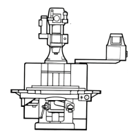
Details on the standard cutter guard and its importance for operator safety.
Explains legal requirements and user responsibility for cutter guards.
Procedures for preparing the installation site, including foundation and clearances.
Details on electrical supply and connection requirements for the machine.
Step-by-step guide for replacing an axis drive unit, including adjustments.
Overview of the control system and procedure for fitting a new controller.
Procedure for resetting software limits after component changes.
Procedures for replacing X and Y axis drive motors.
Procedures for removing X and Y axis ballscrew assemblies.
Steps for diagnosing spindle start problems and control display errors.
Steps for diagnosing control display errors and voltage-related faults.
Steps for diagnosing power enable issues and motor overload conditions.
Steps for diagnosing reference point issues and machine parameter entry.
Steps for diagnosing reference operation and relay faults.
Steps for diagnosing axis drive indicator lights and motor faults.
Steps for diagnosing joystick operation and system error messages.
Steps for diagnosing positioning errors, programming issues, and tool compensation.
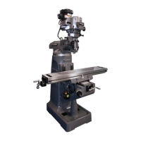
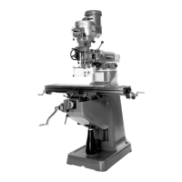
| Type | Vertical Milling Machine |
|---|---|
| Spindle Speed Range | 60 - 4200 RPM |
| Weight | 2300 lbs |
| Spindle Taper | R8 |
| Model | Series 2 |
| Y-Axis Travel | 12 in |
| Z-Axis Travel | 16 in |