Page 2 of 3
NOTICE: Do not tighten each screw in a single step as it may result in a warped crankcase cover. Step-
torque all bolts to approximately 1/3 of the final torque, then 2/3 of the final torque, then finally to the full
torque value.
Starter Bolt Torque
When installing the starter motor to the cylinder, ensure the wires are properly routed behind the starter motor
then start the bolts by hand. Step-torque the bolts (see NOTICE above) until the final torque is achieved.
Final torque is 165 lb-in (18.6 Nm).
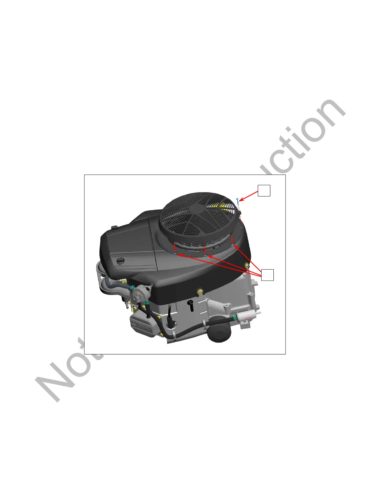
Static Screen Installation
Some engines are equipped with a static screen over the rotating air intake screen. The screen is attached
with screws (A, Figure 2) and tabs (B) that snap into the blower housing. After snapping the tabs into the
slots of the blower housing, install the screws and tighten to 15 lb-in (1.7 Nm).
Figure 2
Governor Gear Thrust Washer Installation
Some engines are equipped with a tabbed thrust washer (A, Figure 3) instead of a flat thrust washer. When
installing the tabbed version, apply clean engine oil to the governor pin and the face of the thrust washer, then
install the washer with the tab (B) facing into the cylinder and located between the two cylinder ribs as shown.
Install the governor gear, retaining ring, and governor cap (Figure 4) on the pin. Pull up on the governor
assembly to ensure it is secured by the retaining ring, then press it down again before final assembly of the
engine.
B
 Loading...