strip G onto points H and I.
5. If present: Attach the aerials to supports J and M at points K and L.
6. Tighten all nuts and bolts to the torque indicated in the drawing.
7. Saw out the indicated section in accordance with figure 2, 2a, 2b.
8. Place the two PE foam blocks as sealing in the chassis members.
9. Replace the element removed in step 1 and 2 except for the buffer
beam.
For dismantling and fitting the vehicle parts, see the site handbook.
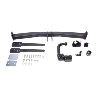
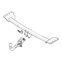
For fitting instructions and attachment method, see drawing.
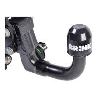
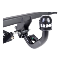
See the assembly manual supplied for instructions on fitting the remo-
vable ball system.
NOTE:
* Should this installation process entail the cutting of the bumper –
conformation MUST be obtained by the installation engineer of the
customer’s acceptance prior to completion. Brink Towing Systems
B.V. do not accept responsibility for any matters arising as a result of
this miscommunication.
*All measurements are in mm!
* The dealer should be consulted for possible necessary adjustment(s) "of
the vehicle".
* Remove the insulating material from the contact area of the fitting
points.
* Consult your dealer for the maximum tolerated pull weight and ball hitch
pressure of your vehicle.
* Do not drill through electrical-, brake- or fuellines.
* Remove (if present) the plastic caps from the spot welding nuts.
* This fitting instruction has to be enclosed in the vehicle documents after
fitting the towbar.
* Brink Towing Systems B.V. is not liable for damage caused directly or
indirectly by incorrect assembly, including the use of unsuitable tools,
the use of other assembly methods and means than the ones outlined,
and the incorrect interpretation of these assembly instructions.
MONTAGEANLEITUNG:
Achtung! Eine Anhängerkupplung kann nur montiert werden, wenn ein
zweiter Ventilator vorhanden ist!
Vor Beginn des Einbaus ist anhand der Typplakette der Anhänge -
kupplung festzustellen welches Bild in der Einbauanleitung maßge-
bend ist.
1. Die Stoßfänger einschließlich des Stoßbalkens vom Fahrzeug abmon-
tieren. Der Stoßbalken wird nicht mehr benötigt. Schrauben wieder
anbringen Siehe Abbildung 1, 1a, 1b, 1c.
2. Die Profile A im Fahrgestellträger anlegen und bei den Punkten B halb-
fest befestigen.
3. Die Anhängervorrichtung, soweit erforderlich einschließlich Füllplatte
D und die Halterungen J und M, bei den Punkten C montieren.
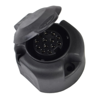
4. Das Brink Connector E einschließlich wegklappbarer Steckdosenplatte
F mit Lasche G bei den Punkten H und I montieren.
5. Falls vorhanden: Die Antennen an die Halterungen J und M bei den
Punkten K und L montieren.
6. Alle Schrauben und Muttern gemäß den Angaben in der Abbildung
festdrehen.
7. Gemäß Abb.2, 2a, 2b das angegebene Teil herausschneiden.
8. Die zwei PE-Schaumblöcke als Dichtung in den Fahrgestellträger ein-
setzen.
9. Montieren Sie das Bauteil, das im ersten und zweiten Schritt entfernt
wurde, außer dem Stoßbalkens.
© 666170/12-03-2019/9
D
 Loading...