EasyManua.ls Logo

Brink Renovent Excellent 300 User Manual

Brink Renovent Excellent 300
44 pages
To Next Page IconTo Next Page
Page #1 background imageLoading...
Page #1 background image
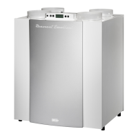
Heat recovery appliance
Renovent Excellent 300/400 (Plus)
STORE NEAR THE APPLIANCE
Installation instructions
Use of this appliance is not permitted for persons, including children, with limited intellectual abilities, serious physical limitations or
lack of experience and knowledge, unless they are supervised by, or have received instructions of how to use the appliance from,
a person who is responsible for their safety.
Children must be supervised to ensure that they do not play with the appliance.

Table of Contents

Other manuals for Brink Renovent Excellent 300

Questions and Answers:

Brink Renovent Excellent 300 Specifications

General IconGeneral
Maximum Airflow300 m³/h
Fan TypeEC fans
BypassAutomatic bypass
Voltage230V
TypeHeat Recovery Ventilation (HRV)
Filter TypeF7 filters
MountingWall or ceiling
Frost ProtectionIntegrated frost protection

Summary

Delivery

Scope of Delivery

Details the components included in the delivery package of the unit.

Application

Version Types

Lists the available types and configurations of the Renovent Excellent 300/400 unit.

Version

Technical Information

Provides key technical specifications, dimensions, and performance data for the unit.

Fan Graphs

Illustrates fan performance curves relating flow rate to static pressure.

Exploded View Appliance

Shows a detailed breakdown of the appliance components with numerical labels.

Connections and Dimensions

Details the physical dimensions and connection port locations for the unit.

Operation

Description

Explains the basic functionality and automatic operation of the heat recovery appliance.

Bypass Conditions

Defines the conditions under which the bypass valve opens and closes.

Frost Protection

Describes the intelligent frost control system to prevent freezing.

Renovent Excellent Plus Version

Highlights the additional features and connectors of the Plus version.

Installation

Installation General

Outlines the general steps and regulations for installing the appliance.

Placing the Appliance

Provides guidelines for mounting the unit securely and level.

Connecting the Condensate Discharge

Details how to connect the condensate drainpipe to the appliance.

Connecting Ducts

Explains how to connect the air supply and extract ducts to the unit.

Electric Connections

Covers the electrical connections for power, switches, and communication protocols.

Display

General Explanation Control Panel

Explains the LCD display and control buttons for operating the unit.

Operating Mode

Describes how the display shows status, air flow, messages, and faults.

Status System Fan

Explains the fan status indicator and associated numbers on the display.

Display Air Flow Rate

Details how the current air flow rate is shown on the display.

Message Text for Operating Mode

Lists and explains various message texts that can appear on the display.

Settings Menu

Guides users on how to adjust appliance settings via the control panel.

Readout Menu

Explains how to view current sensor values and performance data.

Service Menu

Describes how to access and view fault messages for troubleshooting.

Putting into Operation

Switching the Appliance On and Off

Details the procedures for powering the unit on and off via software or plug.

Setting the Air Flow Rate

Explains how to adjust the ventilation air flow rates for different operating modes.

Other Settings Installer

Mentions other adjustable settings for installers.

Factory Setting

Describes how to reset all settings to their original factory values.

Fault

Trouble Shooting

Provides guidance on identifying and resolving appliance faults.

Display Codes

Explains the meaning of fault symbols and codes displayed by the unit.

Fault Code

Lists common fault codes, their causes, and recommended actions for the installer.

Maintenance

Filter Cleaning

Details the procedure for cleaning or replacing the air filters and resetting the indicator.

Maintenance

Outlines installer maintenance tasks for the heat exchanger and fans, recommended every three years.

Electric Diagrams

Basic Diagram

Presents a high-level overview of the unit's electrical connections.

Wiring Diagram

Provides a detailed wiring schematic for the appliance's components.

Electric Connections Accessories

Connections Connectors

Describes the purpose and location of various connectors (X1, X2, X14, X15).

Connection Examples Multiple Switch

Illustrates how to connect different types of multiple switches.

Multiple Switch with Filter Indication

Shows wiring for a multiple switch with filter status indication.

Wireless Remote Control (without filter indication)

Illustrates connecting a wireless remote control receiver and transmitters.

Additional Multiple Switch with Filter Indication

Wiring example for an additional filter-indicating multiple switch.

Additional Multiple Switch with Wireless Remote Control

Wiring example for an additional wireless remote control switch.

Couple Through eBus Contact

Explains how to link multiple units via eBus for synchronized operation.

Connection RH (humidity) Sensor

Details the connection of a humidity sensor to the control board.

Wiring Diagram Postheater Connection

Shows wiring for connecting a postheater or extra preheater to the Plus version.

Connection Example Geo Heat Exchanger

Illustrates connecting a geo heat exchanger to the Plus version unit.

Connecting External Switch Contact

Explains how to connect external switches or relay contacts to the Plus version.

Connection to 0-10 V Input

Details connecting 0-10V input devices like humidity or CO2 sensors to the Plus version.

Service

Exploded View

Provides a visual breakdown of the appliance for part identification.

Service Parts

Lists available spare parts with their article codes and descriptions.

Setting Values

Air Flow Rate Mode Exc. 300: Mode 0

Configures the initial air flow rate for mode 0 on the Renovent Excellent 300.

Related product manuals