CHAPTER 3 THEORY OF OPERATION
3-18
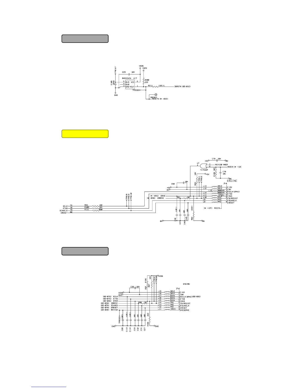
The reset IC is a RN5VD42A. The reset voltage is 4.2V (typ.) and the LOW period of reset is
80ms (typ.)
Fig. 3-22
1.3.9 Engine I/O
Fig. 3-22 shows the engine interface circuit. The interface with the engine PCB is by full-
duplex synchronous serial method.
Fig. 3-23
Fig. 3-23 shows the engine interface circuit. The interface with the engine PCB is by full-
duplex synchronous serial method.
Fig. 3-24
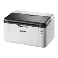
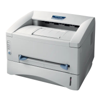
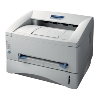
HL-1450/1470N
HL-1450/1470N
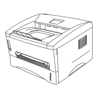
HL-1230/1440
Download Free Service Manual and Resetter Printer at http://printer1.blogspot.com
 Loading...