CHAPTER 4 DISASSEMBLY AND RE-ASSEMBLY
4-37
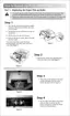
(17) Remove the bind B tite 3x10 screw to remove the eject sensor PCB ASSY.
(18) Disconnect the connector for the thermistor relay PCB ASSY.
(19) Remove the bind B tite 3x10 screw to remove the thermistor relay PCB ASSY from the FU
frame lower.
Fig. 4-60
(21) Release the paper eject actuator from the hook on the FU frame lower, and then slide the
paper eject actuator to the right direction to remove the paper eject actuator and the eject
actuator spring from the FU frame lower.
Fig. 4-61
Screw, bind B tite 3x10
Eject sensor PCB ASSY
FU frame lower
Thermistor relay
PCB ASSY
Eject paper spring
Paper eject actuator
(hook)
FU frame lower
Screw, bind B tite 3x10
 Loading...