CHAPTER 4 DISASSEMBLY AND RE-ASSEMBLY
4-48
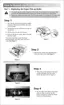
(7) Remove the three tapes on the harnesses and release the harness from the hooks.
(8) Remove the four cup S tite 3x6 screws from the drive sub ASSY A and remove the spring,
extension P/R from the gear 60 P/R.
(9) Disconnect the connectors for the main motor ASSY and the toner LED PCB unit.
(10) Remove the drive sub ASSY A from the main frame.
Fig. 4-76
!
CAUTION:
• Be sure to hold the pendulum gear 30 when removing the drive sub ASSY A in order not to
lose the friction spring fitted under the gear (name).
• Be careful not to lose the joint spring on the develop joint when removing the drive sub
ASSY A.
Tapes
Screw, cup S tite M3x6
Main frame
Drive sub ASSY A
Main motor
ASSY
(hooks)
Screw, cup S tite M3x6
Spring, extension P/R
Lock lever
springs
Gear 60 P/R
 Loading...