CHAPTER 4 DISASSEMBLY AND RE-ASSEMBLY
4-50
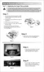
(10) Disconnect the two connectors for the solenoid relay PCB to remove the solenoid unit
from the drive unit.
(11) Release the two hooks and remove the solenoid ASSY 04C4 (red) and the solenoid ASSY
04C5 (black) from the unit.
Fig. 4-79
(12) Place the main frame so that the drive unit side is at the right as the figure shown below.
(13) Remove the bind M3x4 screw to remove the feed solenoid ASSY from the main frame L.
!
CAUTION:
Be sure not to lose the solenoid return spring F/R when removing the clutch lever F/R.
(15) Remove the clutch lever F/R from the main frame.
Solenoid ASSY 04C4 (red)
(hook)
(hook)
Solenoid unit
Solenoid ASSY 04C5 (black)
Clutch lever F/R
Feed solenoid ASSY
Screw,bind M3x4
Screw,bind M3x4
DX guide rail L
Main frame
Clutch lever MP
Clutch lever 04C4
Solenoid release
spring P/R
Solenoid release
spring P/R
Solenoid return
spring F/R
Plunger
Plunger
Bind M 2x4
 Loading...