3-76
Confidential
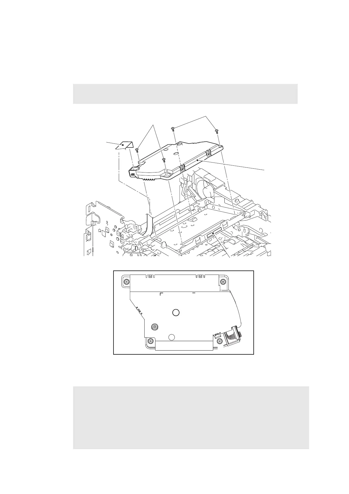
9.19 Laser unit
(1) Disconnect the laser unit flat cable from the laser unit.
(2) Remove the four taptite cup S M3x8 SR screws, and remove the laser unit from the
machine.
Fig. 3-104
Harness routing: Refer to “1.Main PCB ASSY” and “6.Laser unit” .
Note:
• Be careful not to touch the lens of the laser unit.
Assembling Note:
• When attaching the laser unit, tighten the screws in the following order: upper right,
lower right, lower left and upper left.
• When connecting the flat cable(s), insert it straight. After insertion, check that the cable
is not at an angle.
• After replacing the laser unit, attach the laser serial number label of the new laser unit
on the scanner plate as shown in the illustration above.
Laser unit flat cable
Taptite cup S M3x8 SR
Laser unit
Taptite cup S M3x8 SR
1
2
3
4
Laser serial number label
 Loading...