sss
™
1143 page 10
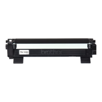
5. Install the contact side end plate onto the cartridge (Figure 26a).
Install the developer roller spring and support bearing onto developer
roller (Figure 26b). Using a Phillips screwdriver, secure end plate with
a screw (Figure 26c).
Figure 26a
Contact Side End
Plate
Figure 26b
Spring
Support
Bearing
Figure 26c
Screw
Phillips
Screwdriver
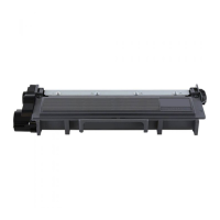
6. On the drive side install the gears and spring in the order shown in
Figure 27a. Install the flag gear spring as shown in Figure 27b.
Figure 27a
Idler Gear
Agitator Gear
Flag Gear
Flag Gear
Spring
3
2
1
4
Figure 27b
Flag Gear
Spring
Note: See page 14 for instructions about resetting the flag
gear.
7. Place the drive side end plate onto the cartridge and secure with
three screws (Figures 28a and 28b).
Figure 28a
Figure 28b
Screws
Phillips
Screwdriver
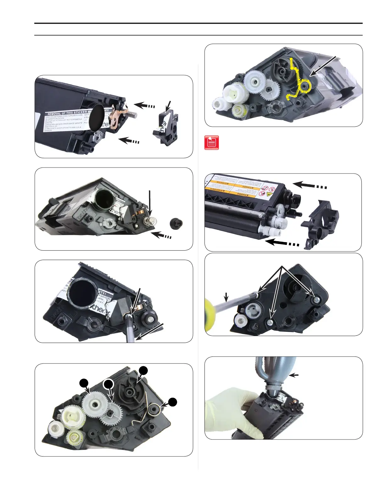
8. Fill the cartridge with qualified toner as shown (Figure 29).
Figure 29
Toner
assembling The CarTriDge
 Loading...