MAINTENANCE PROCEDURES
On approved studded tracks, replace
broken or dam aged studs immediately.
If your track shows signs of deteriora-
tion, it must be replaced immediately.
When in doubt, ask your dealer.
WARNING
Riding with a damaged track or
studs could lead to a loss of con-
trol, resulting in a risk of serious
injury or death.
For complete information on traction
enhancing products, refer to the sec-
tion entitled
TRACTION ENHANCING
PRODUCTS
in the
SAFETY INFORMA-
TION
section at the beginning of this
Operator's Guide.
Track Tension and Alignment
NOTE: Track tension and alig nment
are interrelated. Do not adjust one
without the other.
WARNING
To prevent serious injury to indi-
viduals near the snowmobile:
– NEVER stand behind or near a
moving track.
– Always use a wide-base snow-
mobile stand with a rear deflec-
torpanelifitisnecessarytoro-
tate track.
– When the track is raised off the
ground, only run it at the lowest
possible speed.
Centrifugal force could cause de-
bris, pieces of torn track, or an en-
tire severed track to be violently
thrown backwards out of the tun-
nel with tremendous force.
Track Tension Verification
NOTE: Ride the snowmobile in snow
about 15 to 20 minutes prior to
adjust-
ing track tension.
1. Remove tether cord cap from e
n-
gine cut-off switch.
2. Lift rear of vehicle and support it off
the ground.
CAUTION Use proper lifting
techniques, notably using your legs
force. Do not attem pt to lift the rear
of vehicle if it is above your limits.
3. Allow rear suspension to fully ex-
tend.
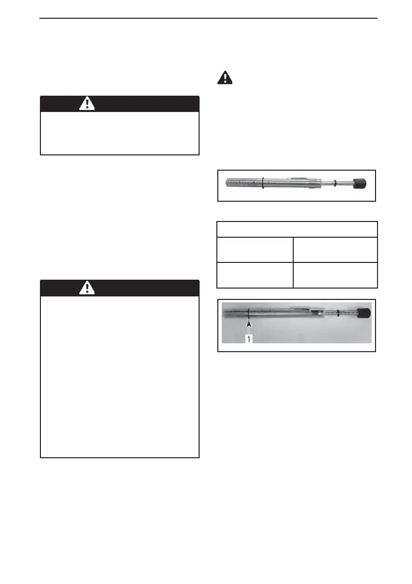
4. Use the TENSIOMETER (P/N 414
348 200).
414348200
5. Set deflection using bottom O-ring.
DEFLECTION
EasyRide
suspension
40 mm to 45 mm
(1.575 in to 1.772 in)
All other models
40 mm to 50 mm
(1.5 in to 2 in)
mmr2009-133-003_b
DEFLECTION SETTING
1. Bottom O-ring set to specification
6. Place upper O-ring to 0 kgf (0 lbf).
7. Position the tensiometer on track,
halfway between front and rear idler
wheels.
8. Push the tensiometer downwards
until bottom O-ring (deflection) be
aligned with the bottom of slider
shoe.
______________
117