BRP-Rotax
INSTALLATION MANUAL
SYSTEM DESCRIPTION
For a detailed System description refer to the latest issue of the Operators Manual (OM).
SYSTEM LIMITATIONS
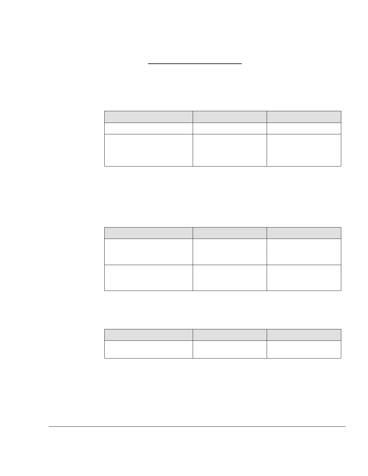
Induction air
intake
Following requirements may be used:
System Limit
Min. Max.
Flow rate
400 kg/h
Pressure loss between ambi-
ent pressure and compressor
in pressure, caused by the
airfilter.
10 mbar (0.14 psi)
Icing in the area of the air intake needs to be avoided. The prevention of icing lies within
the aircraft manufacturer’s responsibility.
Airbox reference
pressure
The reference pressure of the fuel system is the airbox pressure.
Induction air in-
take ducting
System Limit
Min. Max.
Intake pressure loss (Engine
Speed: 5500 ±50 rpm;
Airflow: 360-366 kg/min)
85 mbar (1.23 psi)
Intake pressure loss (Engine
Speed: 5800 ±50 rpm;
Airflow: 384-396 kg/min)
90 mbar (1.30 psi)
PCV ducting All pneumatic connections leading from and to the Pressure Control Valve (PCV) may not
be changed. Changes in length and diameter of the connections will have an significant ef-
fect on the wastegate control. Depending on the installation heat protection may be
required.
System Limit
Min. Max.
Bending radius on tube
centerline
60 mm (2.36 in.)
Valid installation
positions
The intercooler as well as the PCV must be installed vibration-decoupled from the engine.
Compressor
housing
The turbo compression housing must not be rotated. The wastegate functionality can be
affected.
Effectivity: 916 i A / C24
Edition 0/Rev. 1
72–60–00
Page 3
December 01 2023

 Loading...


