Gain
Calibration
Zero
Calibration
Gain
Calibration
Zero
Calibration
_..
OODDDDDDDDDDDDDDDDDDDDDDDDDDDDDDDDDDDDDODODODODDDD
oc
Bruel
& Kjaar
50
00
oc
30
60
10
20
0
0
10
20
30
'
QP
0102
Air Temperature Surface
Plane
Radiant Temperature Temperature
Asymmetry
Dewpoint
700
W/m
2
600
500
400
300
200
Incident
Power
m/s
1
0,8
0,6
0,4
0,2
0,0
Air Velocity
100
% Bruel & Kjaar
10
kPa
80
60
40
20
0
Relat1ve
Humidity
8
6
4
2
0
Vapour
Pressure
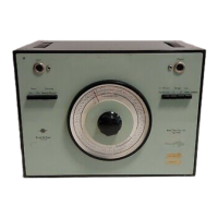
Fig. 5.3.a.
Scaling
of
Recorder
Paper
(S.I. Units)
850019
DODDDDDDDDDDDDDDDDDDDDDDDDDDODODDDODDDDDDDDODDDDDD
OF
Bruel & Kjaar
125
250
OF
75
150
50
100
25
50
0
0
50
'
'
QP
0102
Air Temperature Surface
Plane
Radiant Temperature Temperature
Asymmetry
Dewpoint
250
Btulf
t2
h
210
170
150
130
90
50
Incident
Power
200
ft/min
160
120
100
80
40
0
Air Velocity
100
% Bruel & Kjaar
10
kPa
80
60
40
20
0
Relative
Humidity
8
6
4
2
0
Vapour
Pressure
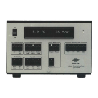
Fig. 5.3.b.
Scaling
of
Recorder
Paper
(Imperial
Units)
850020
A higher resolution can be obtained by lining the zero volt signal up with the right-hand
side
of
the Recorder Paper
or
by changing the SENSITIVITY settings on the 2317.
Note: For the GAIN calibration the Level Recorder should always be connected
to
the
"Y-Out''
socket of the Analyzer. Therefore,
if
real-time
measurements
of
either instanta-
neous air
velocity,
or
incident radiation on the B face
of
the Radiant Temperature Trans-
ducer are required,
calibration should be performed using the
"Y-Out''
socket
of
the
Analyzer.
Once calibration
of
the gain has been accomplished, the Cable should be disconnected
from the
"Y-Out''
socket and reconnected to the
"X-Out"
socket
of
the Analyzer. The
2317 is now
calibrated and ready
for
use in the recording
of
measurements.
5.1.3. Real-Time Recordings Using Level Recorder Type 2317
1.
Connect and calibrate the Level Recorder as described in Sections
5.1.1
and 5.1.2.
2.
Connect the Transducers
to
the Analyzer as described in Section 3.4.1.
45
 Loading...