output
representing
the
tuned
fre-
quency, on a
logarithmic
scale. Th is
is intended
for
controlling
the
posi-
tion
of
the
recording paper on
the
portable Level Recorder Types
2306
and
2309.
A
switch
on
the
rear
panel of
the
1
623
selects
either
for-
wards and backwards paper move-
ment
or
forwards
(increasing fre-
quency) paper
movement
only
.
Unless
the
Level Recorder Type
2306
is modified
the
recording
paper can
only
be fed in
the
for
-
ward
direction
.
Where
the
tuned
fre-
quency falls, for example due to a
reduction of
machine
r.p.
m.,
the
paper feed
will
stop. The paper feed
will
commence
only
if
that
fre-
quency (or r.p.m.) is reached and ex-
ceeded again .
Modification
Kits
for
the
Level Re-
corder Type
2306
to enable
it
to
run both backwards and
forwards
are: Kit No.
WB
0250
for
2306's
with
serial
No
.
lower
than
718
058.
Kit No.
WB
0329
for
2306's
with
serial No.
718
058
and
higher.
Two-Channel Level Recorder Type
2309
may be run in both
forward
and backward directions
under
con-
trol
from
the
1
623.
The second
form
of
synchroniza-
tion
signal provided is a
DC
ramp
voltage
which
is
logarithmically
pro-
portional
to
the
filter
tuned
fre-
quency. This operates in both direc-
tions and is intended
for
controlling
one of
the
axes of
the
X-Y Recorder
Type
2308
.
Power
Supply
The
internal
power
supply con-
sists of six, 4
Ampere
-
hour
capacity
Nickel Cadmium rechargeable cells.
Their capacity is
sufficient
to cover
a
continuous
operating
time
of 8
hours. The separate battery
charger, Type
ZG
0113,
supplied
can recharge
the
cells
from
a com-
pletely
discharged condition in
about
14
hours.
Alternatively, an external
DC
power supply of + 6 V
to
+ 1 5 V can
be used
to
power
the
instrument.
The external
power
supply and bat-
tery charger are connected
through
a socket on
the
rear panel of
the
1623.
4
0,25
J . I I I
Note: Valid
for
denominator settings D < 10
for
D > 10,
multiply
Time by
-RJ
I I I
and
multiply
Sweep
Rate
by
~--1-----l
250
500
Frequency (Hz)
760863
/ 1
Fig.5.
Chart
for
determining
the
recommended
maximum
logarithmic
frequency
sweep
rate
and
the
recommended
minimum
frequency
sweep
time
for
filtered
signal
inaccuracy
<-1
dB
(additional
to
specified
filter
gain
accuracy)
:If
CA.UttON
CH
ll.ltGE VOLTAGE
MOS
T ONLY
IE
APPUED
WHEN USING
R ECHAIIGEAB
LE
BATTEIIIES
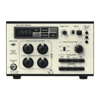
Fig.&. Rear panel
view
of
Tracking
Filter
Type
1623
Photoelectric Tachometer
Probe
MM
0012
Tracking Filter
Vibration Meter
Chart
Synchronisation
----l
I
I
L
__
_, .•.. :.'
,.,
..
, .
.....
Level
Recorder 2306 or 2309
or
X-Y Recorder 2308
Filtered
Signal
Fig.7. Typical
instrument
set-
up
for
synchronous
vibration
analysis
760852
 Loading...