constant
charge between
the
electrodes provided
the
time
constant
of
the
charging circuit
is
much longer
than
the
period
of
the
sound pressure varia-
tions. When sound pressure waves are incident
on
the
diaphragm,
the
distance between
the
diaphragm and backplate changes so
the
capacitance
changes and an AC
voltage
is
produced. By careful design,
the
AC
output
voltage waveform can be made similar
to
that
of
the
sound pressure level
waveform through
extended
frequency and
dynamic
ranges.
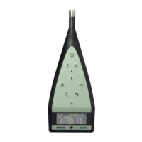
The
microphone supplied with
the
2209
Impulse
Sound
Level Meter
is
the
B & K
Type
4145
One Inch Condenser Microphone. Each microphone
is
supplied with
an
individual calibration chart showing its
complete
technical
specification and its frequency response.
Such
a frequency response curve
is
shown in Fig.4.3.
The
free field response curve
with
Random
Incidence
Corrector UA
0055
(curve F
1
)
has been superimposed and
is
not
supplied
on
an actual calibration chart.
4.3. INPUT STAGE
The
low capacitance
of
the
condenser microphone makes it necessary
to
have a high input impedance
in
the
input stage. This impedance
is
made
up
of
a high resistance
to
ensure a low lower limiting frequency and a low
capacitance
to
ensure minimum
attenuation
of
the
microphone signal.
A simplified circuit diagram
of
a condenser
microphone
and preamplifier
( Fig.4.4) and
the
equivalent circuit ( Fig.4.5) will aid explanation.
The
output
voltage V
0
is
determined from
b.C
(t) E
0
jwRCt
Ct
1 +
jwRC
Sound I\.
pressur_e
____
V
C
1
+
t.C(t)
(t::=~
Microphone
diaphragm
Microphone
I
I
I
I
I
Cs:
Polarization
voltage
Preamplifier
Fig.4.4. Circuit
of
Condenser Microphone and Preamplifier
28
( 1)
17oo5'/J
 Loading...