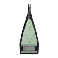
Fig.4.8.
Input
socket
of
Type 2209
With
the
switch
open
(screw
in
its fully anti-clockwise position)
the
capacitor
is
in
circuit and
the
low
frequency
response
of
the
2209
is
as
indicated
by
the
continuous
curves
of
Fig.4.9. With
the
switch closed (screw
in
its fully clockwise position)
the
capacitor
is
short
circuited and
the
low
frequency
response
is
as
in
the
dashed curves
of
Fig.4.9.
4.4.
INPUT OVERLOAD INDICATOR AND
PHASE
SPLITTER
When using
the
2209
in
its linear position, overload
of
the
amplifiers can
be observed on
the
indicating
meter
by
overdeflection
of
the
needle,
but
when weighting
networks
or
external filters are used, certain signal com-
ponents
will be
attenuated
and will
not
reach
the
output
amplifier
and
show
up
on
the
meter. It can
be
seen
therefore
that
while
the
output
amplifier
may
not
be overloaded
the
input
amplifier may well be. Hence an overload
indicator
is
placed immediately
after
the
input
amplifier, as suggested
by
the
I
EC
extension
to
179
for
Impulse
Sound
Level Meters.
If
the
output
voltage exceeds a certain peak value a
monostable
multi-
vibrator
is
triggered.
The
multivibrator
is
kept
in its
"on"
mode
for
about
a
second, during which
time
the
indicator lamp will flash a few times. A phase
splitter
between
the
input
amplifier
and
the
overload indicator ensures
indication for
both
positive
and
negative peaks.
32
 Loading...